CP3 Modification
CP3 Modifications you can do yourself!
Ongoing discussion about this article can be found by Clicking Here.
Original Writeup By Relentless Diesel Performance - http://relentlessdiesel.com
This should help some of you understand how to modify your own CP3 injector pump. We'll get into more detail of CP3's in another article, but for now understand that all you can do is completely fill the plungers with fuel. The CP3 has three plungers and each plunger intakes a certain amount of fuel and expels it into the fuel rail with each injector pump revolution.
Each plunger makes the same length downward and upward stroke on each revolution regardless of how much fuel is commanded. If the plungers were full of fuel the pump would always move the same amount of fuel per revolution and we know that's not true. At light throttle/low power the pump moves very little fuel into the rail. At high power levels the pump moves all the fuel it can.
It's easy to see that the plungers are not always full of fuel on the intake stroke. Our goal as pump modifiers is to make sure the plungers are more full of fuel (therefore moving more fuel into the rail) during high power levels than the stock pump.
There are several restrictions from the time the fuel enters to the CP3 until it gets sucked into the plunger/barrel chamber. As we eliminate each restriction the plunger chamber can fill more completely with fuel.
This article will cover two simple modifications that most anyone can do to increase the fuel delivery from their CP3 pump.
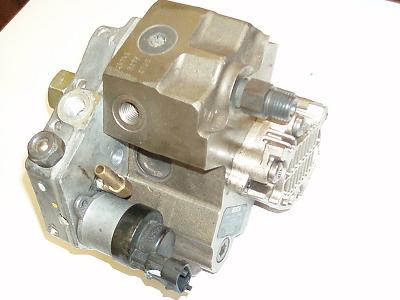
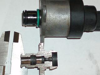
Take a look at the picture below. You'll notice two easily removable pieces bolted to the back of the CP3.
http://www.relentlessdiesel.com/media/cp3mods/cp3.jpg
On the lower right you'll see the fuel control actuator (FCA) which has the black colored electrical connector attached to it. You'll also notice the aluminum housing of the gear pump on the very back. Both of these items are easily removed with the pump still in the truck and cause major restriction to fuel flow.
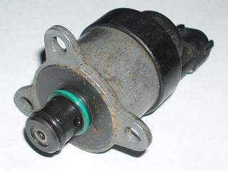
Remove the FCA first. It will look something like this.
http://www.relentlessdiesel.com/media/cp3mods/fcaoriginal.jpg
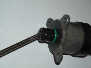
Start with an extremely clean work place.
Using an allen wrench or a cutoff screwdriver pry out the endcap. (We used a torx bit for the pictures, but it deforms the i.d. of the endcap too excessively.)
http://www.relentlessdiesel.com/media/cp3mods/fcapryout.jpg
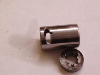
Carefully remove the spring and lightly tap the fca on the table to help slide the metering valve out. (Use extreme caution when handling the metering valve. If it is bent or even scratched it can stick will be useless.)
http://www.relentlessdiesel.com/media/cp3mods/fcavalveout.jpg
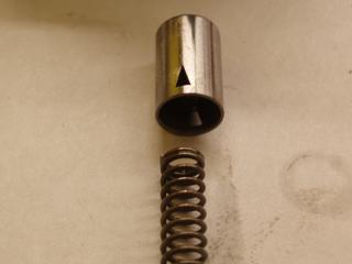
All the fuel that is allowed to enter the plungers must first make it through these two tiny triangular holes in this valve.
http://www.relentlessdiesel.com/media/cp3mods/fcavalveclose.jpg
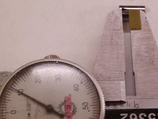
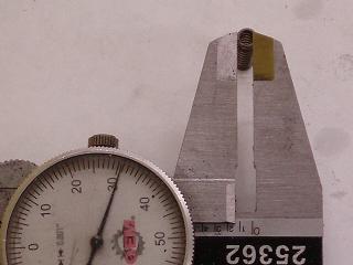
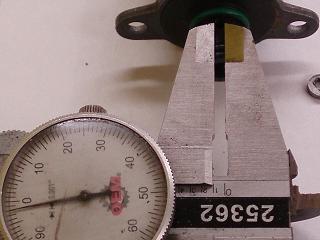
Each triangle is 0.110" high
http://www.relentlessdiesel.com/media/cp3mods/fcavalvelength.jpg
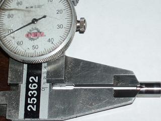
and 0.068" wide
http://www.relentlessdiesel.com/media/cp3mods/fcavalvewidth.jpg
for a total area of 0.00748 square inches between the two. This is equivalvent to a single hole with a diameter of 0.097".
By enlarging these triangles more fuel will be able to get to the plungers. This is the smallest restriction from the inlet of the CP3 all the way into the plunger chamber.
We've tried various shapes which allow more or less flow at each duty cycle (position) of the valve and the one that works the best also happens to be the easiest to machine.
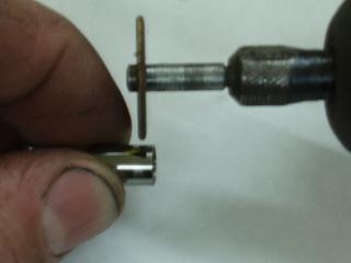
A simple dremel tool cutoff wheel can be used to perform a simple slice into the triangle.
- It is extremely important that you do not modify the tip of the triangle. The tip is crucial to the valves ability to stop and regulate fuel at small flowrates (idling, cruising, etc.)**
http://www.relentlessdiesel.com/media/cp3mods/fcavalvecutting.jpg
Use some gloves or something soft for protection. I don't want to hear complaints that you cut your finger. Don't chuck it up in a vise because you'll damage the valve. BE CAREFUL!!!
Here's an example of a cut valve.
http://www.relentlessdiesel.com/media/cp3mods/fcavalvecut.jpg
You'll need to spend a LOT of time polishing the cut edges both inside and outside with some very fine sand paper. The valve will need to freely slide in and out of the housing without force. If you get in a hurry and force a valve into the housing with a burr of any kind it will scratch the housing and be JUNK. Throw it away and start over.
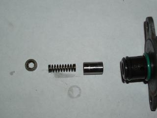
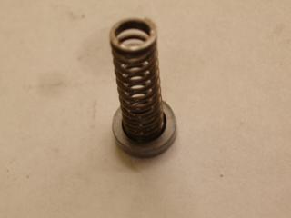
Now take a look at the spring and endcap that you pryed out. Remember they stack like this:
http://www.relentlessdiesel.com/media/cp3mods/fcaendcapspringstack.jpg
You can enlarge the center hole in the endcap, but there's really no use going bigger than 0.130" since that is the I.D. of the spring. Fuel has to travel down the center of the spring on its way out of the FCA.
http://www.relentlessdiesel.com/media/cp3mods/fcaspringid.jpg
Again, I cannot stress deburring all edges with sandpaper and cleanliness enough. You don't have the luxury of a filter to catch your mistakes. What you leave behind goes directly into the pump plungers and then into your $350 a piece injectors.
Insert the valve, spring and press the endcap back into place and you're finished modifying your FCA.
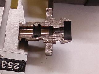
For those of you that want to understand the FCA a little better before modifying it, we have included some cross sectional views to simply it.
Here is the housing cut open.
http://www.relentlessdiesel.com/media/cp3mods/fcaversussection.jpg
Here is a closer view. Look at the first darkened region (left to right). You'll notice two holes. There are four holes total and this is where the fuel enters this valve.
http://www.relentlessdiesel.com/media/cp3mods/fcasectiononly.jpg
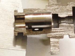
Here is a picture with the valve in place positioned to delver NO FUEL!
http://www.relentlessdiesel.com/media/cp3mods/fcasectionnoflow.jpg
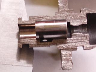
Here is a picture with the valve in place to deliver FULL FUEL FLOW!
http://www.relentlessdiesel.com/media/cp3mods/fcasectionfullflow.jpg
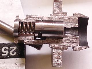
This final picture shows all three parts in place!
http://www.relentlessdiesel.com/media/cp3mods/fcasectionassembled2.jpg
For those of you thinkers out there who think the inlet holes might be a restriction themselves. Here's the math.
http://www.relentlessdiesel.com/media/cp3mods/fcainlethole.jpg
Each hole is only 0.100" but since there are four of them the equivalent hole size is 0.200". MUCH larger than the 0.130" endcap on the other end.
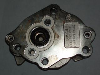
The next restriction we will tackle is the orifices in the gear pump housing.
The gear pump looks like this once it's removed.
http://www.relentlessdiesel.com/media/cp3mods/cp3pumpcover.jpg
The red arrows are pointing to where two aluminum rivets will be. Flip the pump over to have the front side facing upwards and drill out both rivets.
http://www.relentlessdiesel.com/media/cp3mods/cp3pumpfront.jpg
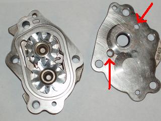
Once you've removed the rivets, you can separate the front pump cover from the gears and rear housing.
http://www.relentlessdiesel.com/media/cp3mods/cp3pumpcoveroff.jpg
The two red arrows here are inlet and outlet ports which can be enlarged. The outlet port is around 0.110" if memory serves me correctly. You can easily enlarge both holes to the 0.140"-0.160" range.
Flow will still be restricted by the 0.130" endcap in the FCA so there's no reason to go overboard here.
Obviously, you'll need to deburr the holes and clean everything up. You can use a 6-32 machine screw from any hardware store to bolt the pump back together if you don't have a rivet gun.
That should do it. Sit back and enjoy the fact that in under an hour you were able to perform the same modifications that some shops charge over $1100 to do.
--Iker42 17:03, 8 November 2007 (EST)