Walbro Aux Fuel Filter Setup
Walbro Fuel Pump + Aux Fuel Filter + Fuel Pressure Gauge Install
Ongoing discussion about this article can be found by Clicking Here.
Original Writeup By 8mpg
Well, I hope you guys think this is helpful. I spent the last 5 hours or so organizing all the photos and doing the writeup. Its going to be LONG but detailed. I hosted all the pictures in a photobucket account so if they die, sorry. I do have these write-ups in PDF format if you guys would like to save them.
Big thanks to Wade (Stacked97) for the help with the install. Anyways, here we go.
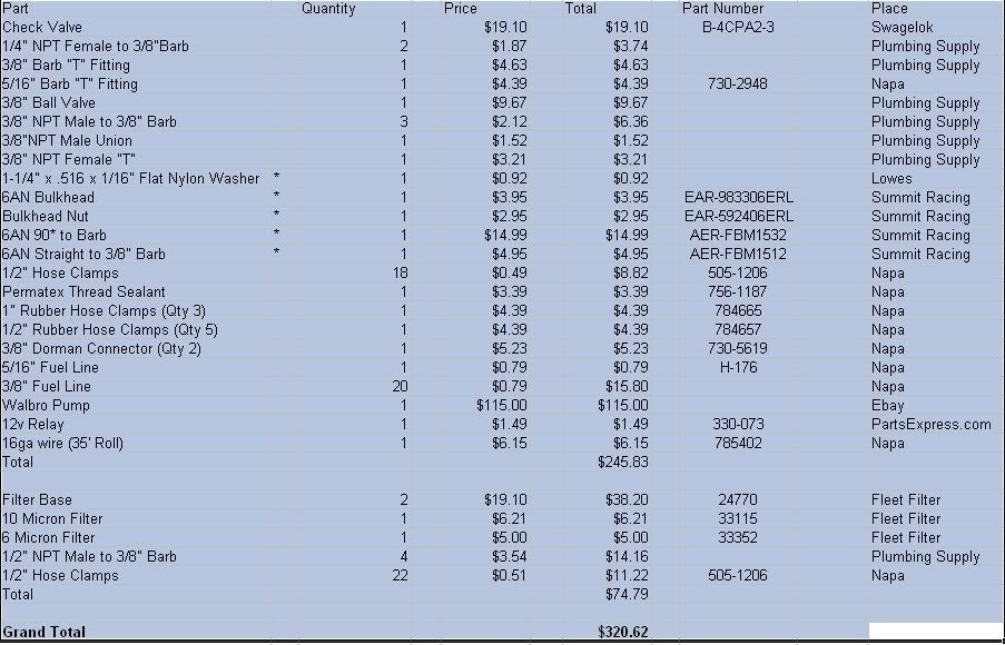
Parts list:
http://i198.photobucket.com/albums/aa222/8mpg_walbro/parts.jpg
Dropping the tank
Tools needed:
15mm Deep Socket
Socket wrench
Flat blade screwdriver
Dikes
11/16 wrench
13/16 wrench
½” Drill bit
Pliers
Hammer
Drill
Catch can or cup
Razor blade
Floor jack/Transmission jack/ATV jack..you pick
Parts needed:
16” 3/8” Fuel line
5’ 3/8” Fuel line
-6AN to barb fitting
-6AN Bulkhead
-6AN Bulkhead Nut
-6AN 90* to barb fitting
(2) ½” Hose clamp
Nylon washer
(2) Zip ties (hopefully 2)
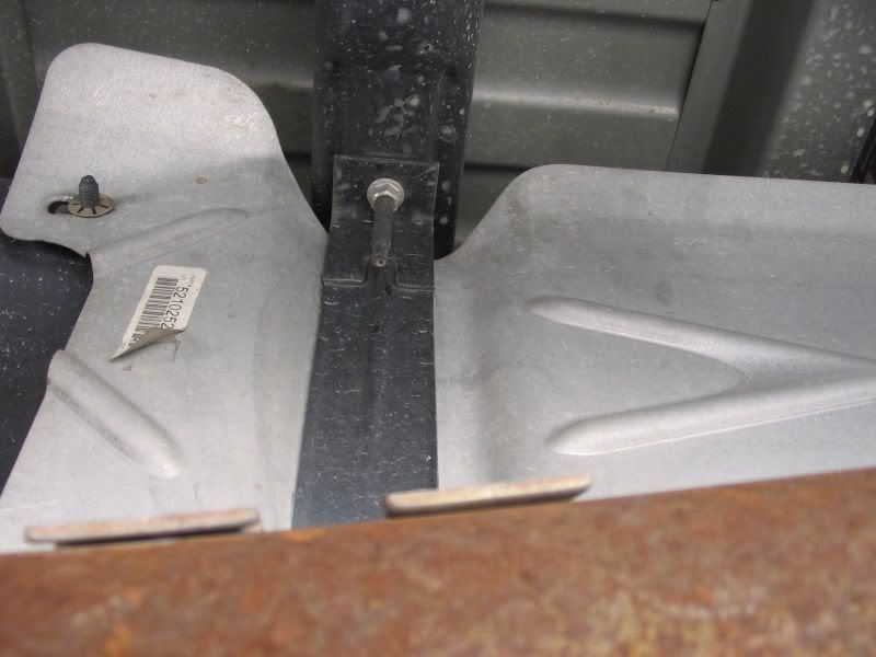
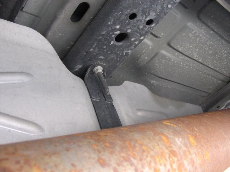
1. Jump under the driver’s side of the truck in front of the rear wheel. You will see the black tank. There are 2 metal straps that hold the tank in.
http://i198.photobucket.com/albums/aa222/8mpg_walbro/Fuel%20Tank/001.jpg
http://i198.photobucket.com/albums/aa222/8mpg_walbro/Fuel%20Tank/002.jpg
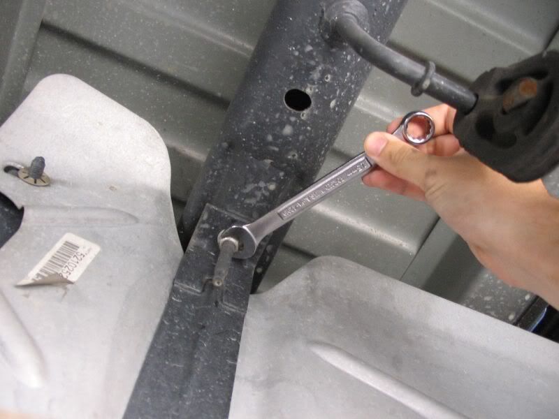
2. Using the 15mm wrench, loosen the two nuts securing the strap
http://i198.photobucket.com/albums/aa222/8mpg_walbro/Fuel%20Tank/003.jpg
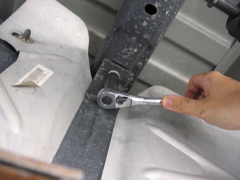
3. After a couple turns, use the 15mm deep socket and wrench.
http://i198.photobucket.com/albums/aa222/8mpg_walbro/Fuel%20Tank/004.jpg
4. Loosen the nuts to until you get them near the end of the bolt. You do not want to take them off yet. You want to drop the tank but let the nuts/straps hold it up still
http://i198.photobucket.com/albums/aa222/8mpg_walbro/Fuel%20Tank/006.jpg
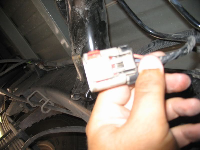
5. Once the tank has dropped a bit, its time to disconnect the stock fuel lines and pump/sender electrical harness. The wiring harness has a red lock on it. Push the red tab towards the rear of the truck. Then push the grey U shaped tab down and disconnect the connector
http://i198.photobucket.com/albums/aa222/8mpg_walbro/Fuel%20Tank/007.jpg
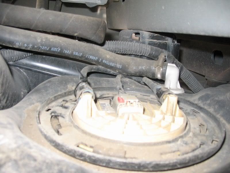
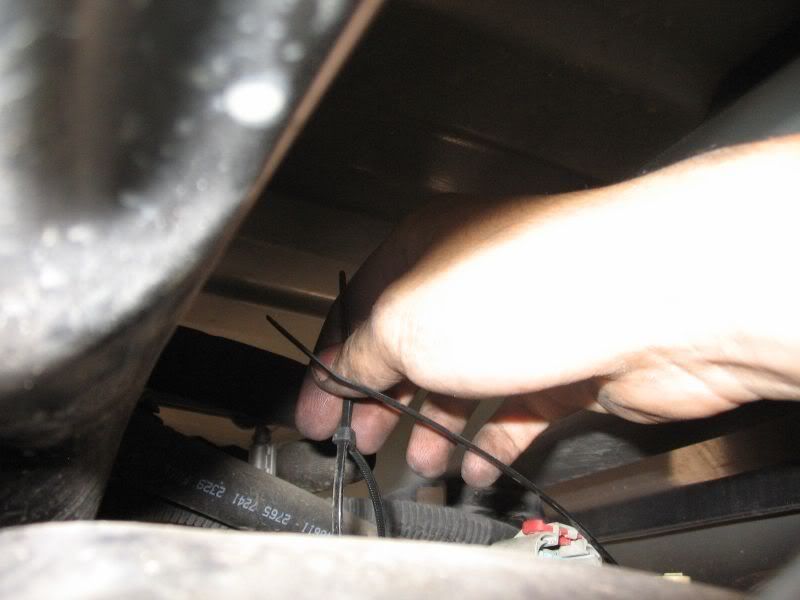
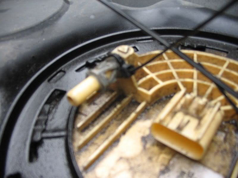
6. To disconnect the fuel lines, loop a ziptie around the fuel line towards the outside of the truck. You want to start the ziptie but do not tighten it yet. Slowly slide the ziptie to the end of the fitting. There are 2 clips that must be pushed down at the same time before you can remove the fuel fitting. You are using the ziptie to clamp down on the two fittings at the same time. One is on the top of the fitting and one on the bottom side. Then push the fuel line off the pump.
http://i198.photobucket.com/albums/aa222/8mpg_walbro/Fuel%20Tank/008.jpg
http://i198.photobucket.com/albums/aa222/8mpg_walbro/Fuel%20Tank/010.jpg
http://i198.photobucket.com/albums/aa222/8mpg_walbro/Fuel%20Tank/011.jpg
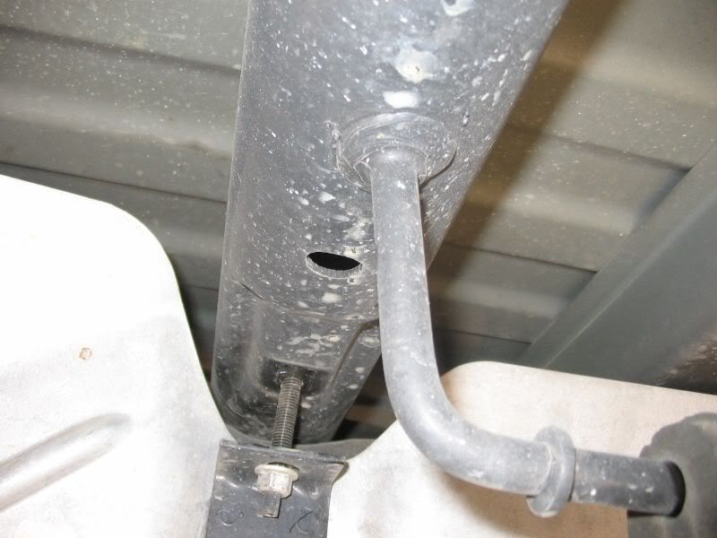
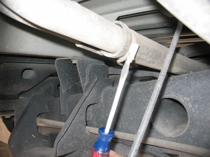
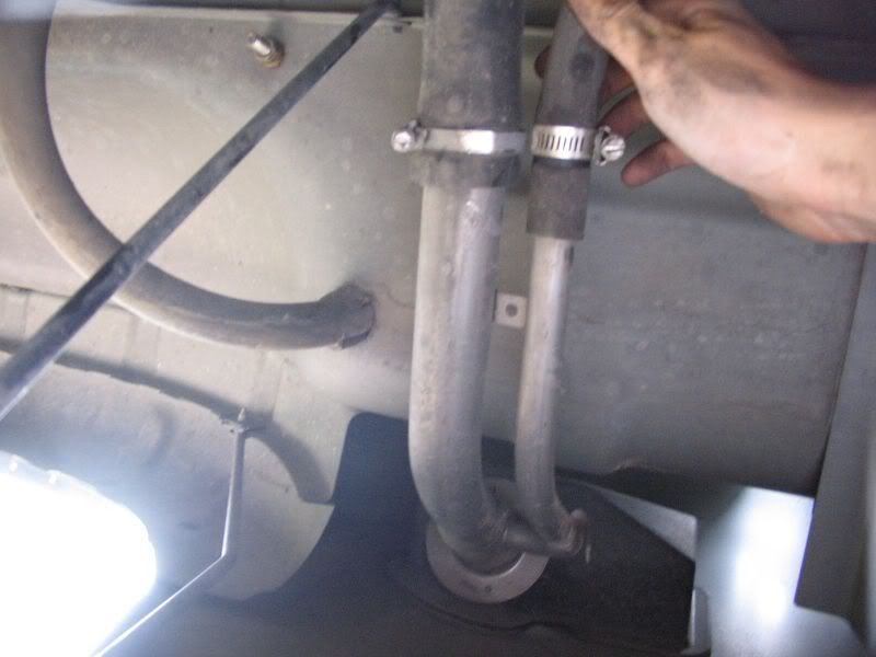
7. Disconnect the fuel filler hose and the vent hose located behind the gas cap. Using the flat blade screwdriver, loosen the hose clamps. Slide the hose off the metal tubing
http://i198.photobucket.com/albums/aa222/8mpg_walbro/Fuel%20Tank/012.jpg
http://i198.photobucket.com/albums/aa222/8mpg_walbro/Fuel%20Tank/013.jpg
8. If you are by yourself, slide a jack under the rear side of the tank and pump it up to hold the weight of the tank. Move to the front and loosen the nut and strap holding the tank in. The strap needs to come out. While holding the tank, pull the strap and rotate it outwards. When you rotate it about ½ way, you push the outside of the strap up to release it from the holder. Let the front side of the tank down and do the same with the rear.
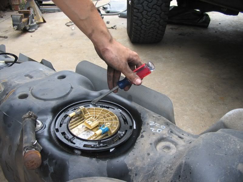
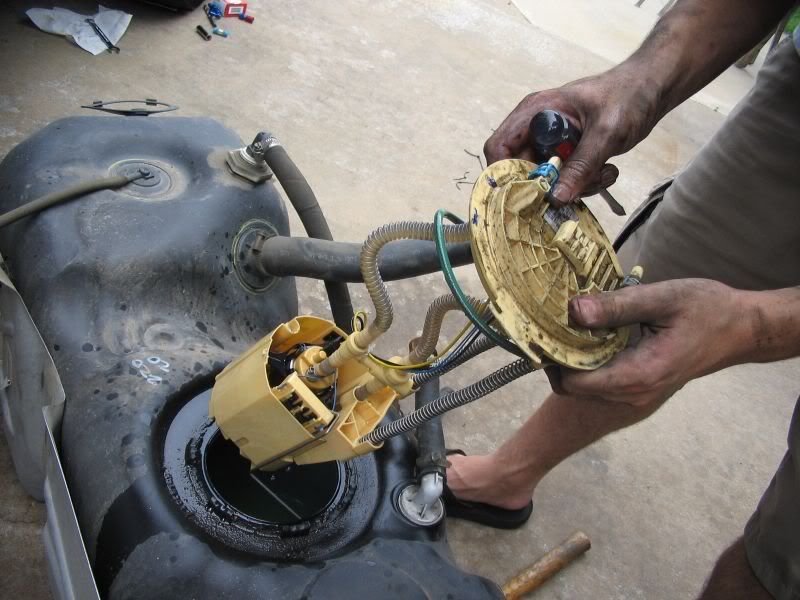
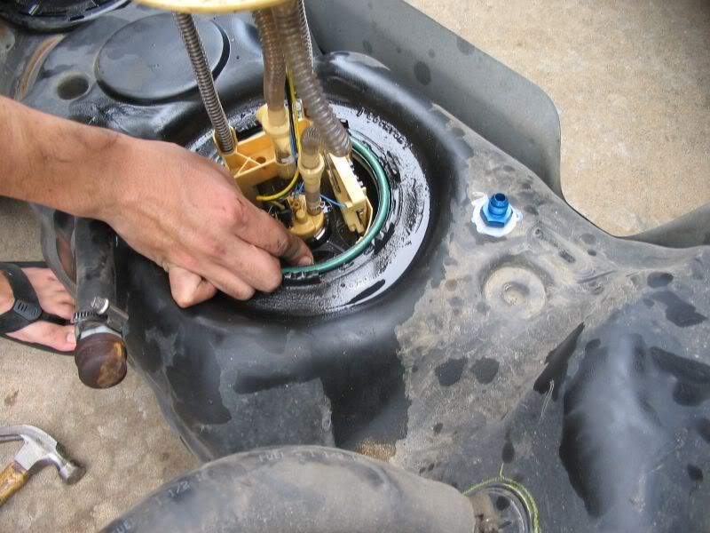
9. Once you get the tank down and out of the truck, its time to take out the sending unit. Using the screwdriver (or a punch if you want to do it proper) and hammer, tap the pump lock ring counter clockwise. Slowly remove the pump. The rear clear plastic hose may need to be pushed in a bit to pull the pump.
http://i198.photobucket.com/albums/aa222/8mpg_walbro/Fuel%20Tank/018.jpg
http://i198.photobucket.com/albums/aa222/8mpg_walbro/Fuel%20Tank/019.jpg
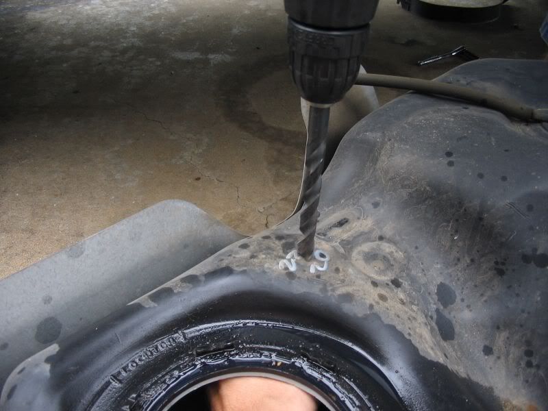
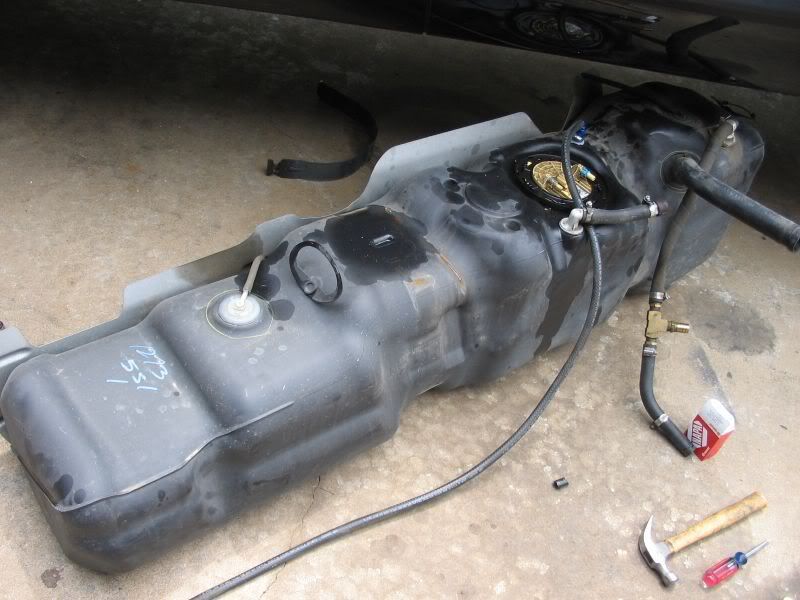
10. Now using the drill and ½ bit, you are going to drill the hole for the bulkhead. Use your catch can or cup and hold it inside the tank where you are going to drill. This will catch the shavings and keep them out of the pumps. Be sure NOT to drill to close to where the strap mounts. I would actually drill about ½ to the front of where the drill bit is on the tank. Mine is a tight squeeze between the strap mount and the fitting.
http://i198.photobucket.com/albums/aa222/8mpg_walbro/Fuel%20Tank/022.jpg
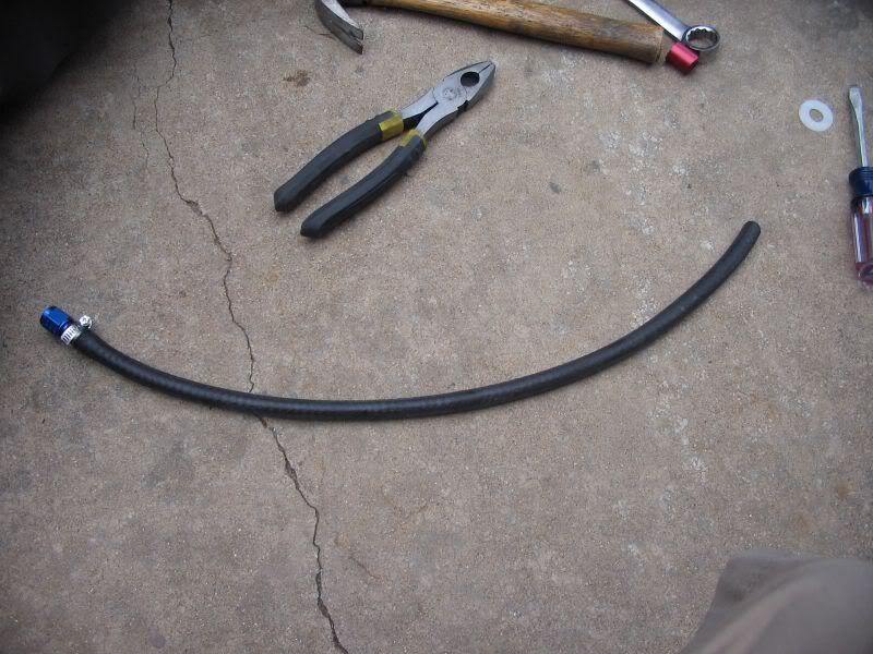
11. Put the nylon washer on the long side of the bulkhead. It’s a VERY tight fit, so you might need to hot it out just a bit with the ½ drill bit. Use the pliers to hold the nylon washer when you do it. Then thread the bulkhead into the hole drilled in the tank. Use the 13/16” wrench to thread it down all the way until its snug. Then use the bulkhead nut and tighten it on the inside using the 13/16” wrench on the top and holding the bulkhead nut on the bottom. Assemble the straight -6AN to barb fitting with the 16” of hose and hose clamp. Attach the assembly to the bulkhead. Using your judgment, cut the hose to length and cut an angle out of the end of the hose to keep the house from sucking to the bottom of the tank. You can use (and I recommend) using the Glacier Diesel Power pickup kit and skip all the AN fittings.
http://i198.photobucket.com/albums/aa222/8mpg_walbro/Fuel%20Tank/024.jpg
http://i198.photobucket.com/albums/aa222/8mpg_walbro/Fuel%20Tank/025.jpg
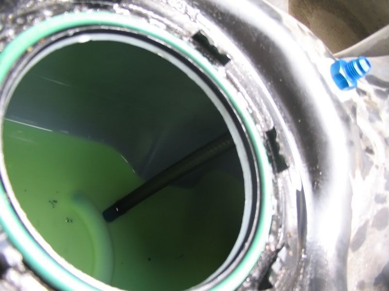
12. Time to put the stock pump back in. Make sure the big O-ring is seated correctly around the tank hole. Its green in the picture. It has a specific channel that it sits in. Pump the pump back in slowly. Push the pump down and put the lock ring back on. Using the hammer and screwdriver, tap the lock ring clockwise to lock the pump in. Then attach the -6AN 90 fitting to the top of the bulkhead and angle it towards the stock pump. The fuel line will follow the stock fuel line. Attach the 5’ fuel line using a hose clamp on the barb end of the 90* fitting.
http://i198.photobucket.com/albums/aa222/8mpg_walbro/Fuel%20Tank/026.jpg
http://i198.photobucket.com/albums/aa222/8mpg_walbro/Fuel%20Tank/027.jpg
13. Install the tank. Just do the reverse procedure of earlier and you will be fine. Set the back on the jack and lift the front. Attach the front strap and start the nut. Go to the back and push the vent line and filler line over the frame rail. Jack up the jack and attach the rear strap. Start the nut on the rear strap. Connect your fuel lines and electrical connector. Make sure the fuel lines “click” so you know they are fully seated. Push the red tab on the electrical connector towards the front of the truck to lock it. Attach the filler neck hose and vent line to the metal tubes and tighten the hose clamps. Tighten down the strap nuts with the deep socket and give it a good tighten with the wrench. Make sure not to crush the new fuel line with the fuel tank. I routed the hose between the truck bed brace and the truck bed.
That’s the hard part… It helps to have a friend pull the tank and put it back in. If you don’t have anyone it can be done by yourself but you better get ready to use both arms and legs at the same time. This is a GREAT time to install a fuel vent mod at the same time. Its worth the $30 and you can do it since you already have the tank out. The fuel vent mod kit can be purchased from http://www.innertruck.com or from http://www.glacierdieselpower.com
Fuel Filter Install
Tools Needed:
Chop Saw
Drill Press
5/16” Drill bit
Measuring Tape
Thread sealant
½” wrench
½” socket
3/8” ratchet
3” 3/8” extension
Sharpie marker
Square
3/8” Allan key
¾” wrench
Welder
Parts Needed:
Fuel filter bases
½”NPT male to 3/8” barb fittings (4)
5/16” x 4” bolts (4)
5/16” lock washers (10)
5/16” nuts (10)
5/16” x 1” bolts (6)
10 micron filter
6 micron filter
1”x2” box tubing (6” length)
1”x ¼” flat stock metal (36” length)
Spray Paint
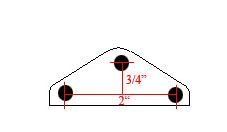
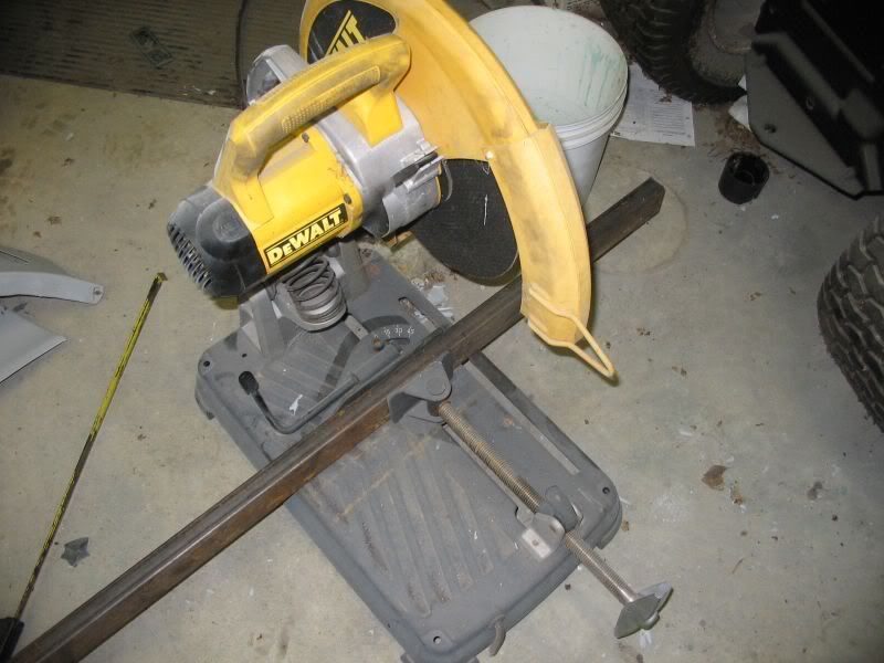
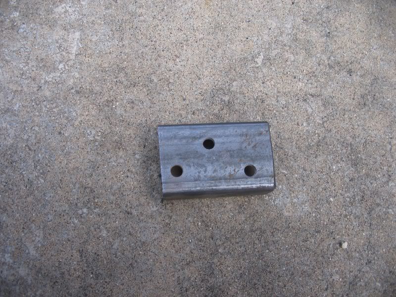
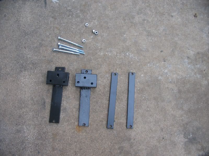
1. Using the chop saw, cut the 1x2 box tubing in 3” sections. You will need 2 sections of tubing. Using the filter base and sharpie, mark the top hole of the base on the box tubing. From there, using the square, offset the top hole ¾” and draw a line. From the outside, mark the bottom line 1” in on both sides. The holes are offset 2” from eachother.
http://i198.photobucket.com/albums/aa222/8mpg_walbro/001.jpg
http://i198.photobucket.com/albums/aa222/8mpg_walbro/002.jpg
http://i198.photobucket.com/albums/aa222/8mpg_walbro/003.jpg
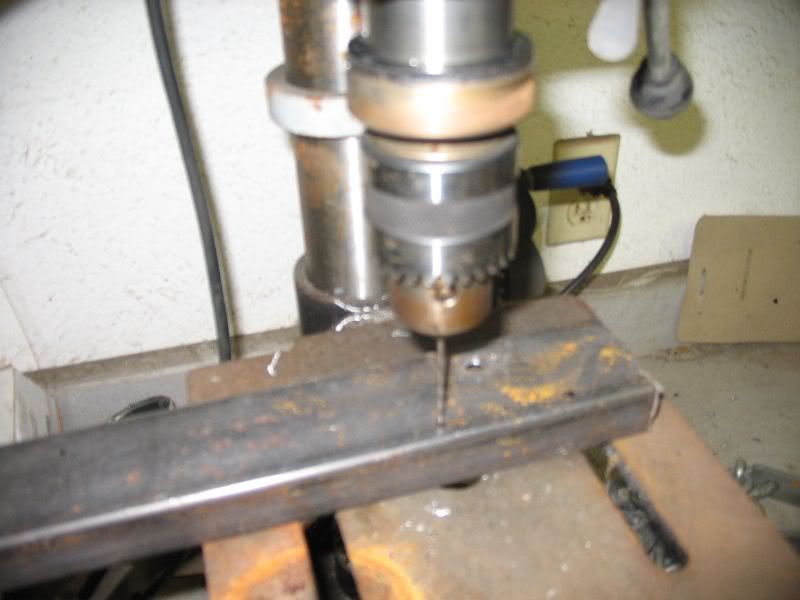
2. Using the drill press and 5/16” bit, drill out the holes you marked with the marker. I like to start the holes with a smaller bit to make sure I get the center…its optional
http://i198.photobucket.com/albums/aa222/8mpg_walbro/004.jpg
http://i198.photobucket.com/albums/aa222/8mpg_walbro/005.jpg
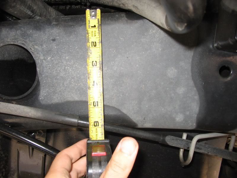
3. The frame rail measures about 6.25”. Cut the flat stock into 4 pieces about 8” long. Drill a 5/16” hole centered at the top about ½” down on all 4 pieces. At this point use the 4” bolt and put them over the frame rail and slide the bolts through them. For now, just tighten the nuts and bolts finger tight until the final mount. These brackets act as a clamp, so pair up the brackets (helps to letter the sets A and B) and put a bracket from A on the inside and the other on the outside. Do the same with set B. Mark the location of where you should drill the bottom 5/16” holes so that the bolts either fit snug on the frame rail or have a bit of space. ¼” of space between the top or bottom of the bolts and the frame rail will not hurt anything. Drill the holes and remount the brackets, clamping the frame rail. This is a picture of the approximate locations for the fuel filter assemblies. *** My brackets were a bit shorter so yours will have a bigger lip on each side of the drilled holes. I cut them to 7”
http://i198.photobucket.com/albums/aa222/8mpg_walbro/006.jpg
http://i198.photobucket.com/albums/aa222/8mpg_walbro/008.jpg
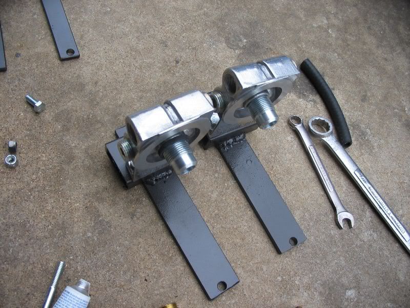
Using the 1x2 box, attach the filter heads using 5/16 x 1” bolts. You don’t need to put the lock washers on yet, this is just a mock up. Find the best height and mark the bottom of the 1x2 box on the flat stock bracket you made. Do the same to the other filter. When you have determined the right height, go ahead and tack the 1x2 on the flat brackets and mock it up again to make sure you are happy with the mount. When you are happy, go ahead and finish weld the brackets and paint them. The brackets will end up looking like below. Go ahead and remount the filter heads using the lock washers and tighten them down for good. *** I used some ¾” wide x ¼” thick straps on the back because I had it laying around.
http://i198.photobucket.com/albums/aa222/8mpg_walbro/009.jpg
http://i198.photobucket.com/albums/aa222/8mpg_walbro/010.jpg
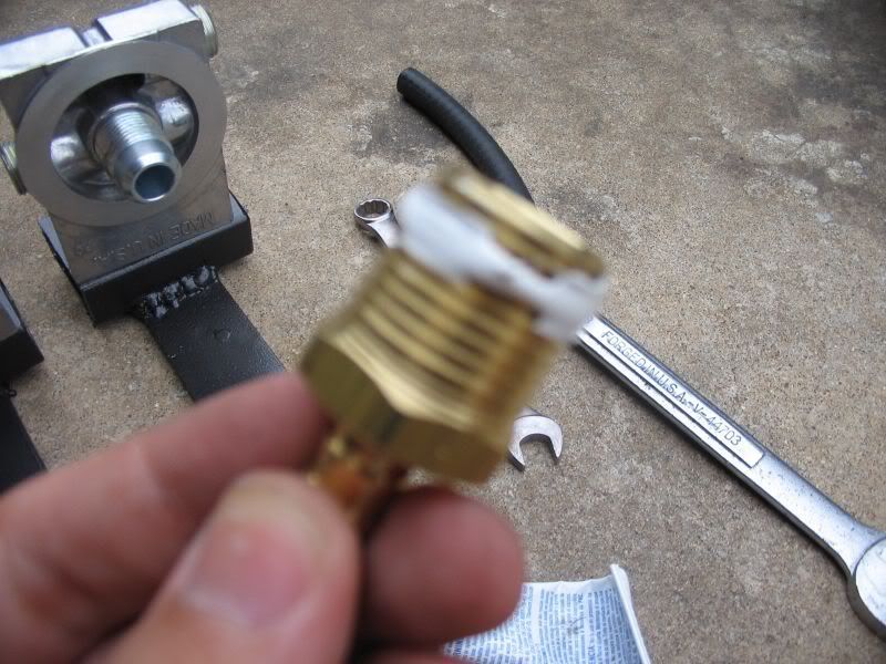
4. Bolt the brackets back on in their final resting position. Tighten the bracket bolts down using the ½” wrench and ½”socket with extension. They will be solid. Now using the thread sealant, apply a small amount all the way around the base of the ½” to 3/8” barbs and tighten them on the filter base using the ¾” wrench. Make note of the arrows and which way they point. You can see in the picture above which ports should be plugged with the provided caps and which receive the barb fittings. Again, using the thread sealant, seal the bottom threads of the ½” plugs and use the 3/8” allan key and tighten them down.
http://i198.photobucket.com/albums/aa222/8mpg_walbro/011.jpg
http://i198.photobucket.com/albums/aa222/8mpg_walbro/012.jpg
http://i198.photobucket.com/albums/aa222/8mpg_walbro/013.jpg
Plumbing the Fuel System
Tools Needed:
Drill
11/64” drill bit
¼” ratchet
¼” 3” extension
3/16” socket
5/8” wrench check
9/16” wrench check
3/16” wrench valve
¾” wrench
7/8” wrench valve
Mini tubing cutter
¼” nut driver or screwdriver
Dikes
3mm allan wrench
Bucket
Parts Needed:
- 12 x 1 machine screws
5/16” flat washer
Big P clamp
Small P clamp
Ring terminal (big enough to fit a #12 screw through it)
½” Hose Clamps (16)
3/8” Hose clamps (5)
3/8” to 3/8” Dorman connector
Zip ties (small and medium sized)
3/8” fuel line (20’)
5/16” fuel line (6”)
Pipe fittings
Barbed fuel filter
10mm x 1 to 3/8” barb (2) supplied with Walbro pump
3/8” Barbed “T” fitting (1)
¼” NPT Male to 3/8” barb (2)
Check valve (1)
5/16” Barbed “T” fitting (1)
3/8” NPT Male to 3/8” barb (3)
3/8” NPT Female “T” fitting (1)
3/8” Ball valve (1)
3/8” NPT Male to 3/8” NPT Male (union) (1)
1. Using a 3mm allan wrench, adjust the lock nut and spring tension nut out to approximately the same as the picture below. The outer nut acts as a lock nut and is backed up and tightened against the inside nut. This is just an approximate, you WILL have to pull it off and adjust unless you have some type of miracle. Using an air compressor does not work at setting the check valve open pressure.
http://i198.photobucket.com/albums/aa222/8mpg_walbro/Plumbing/001.jpg
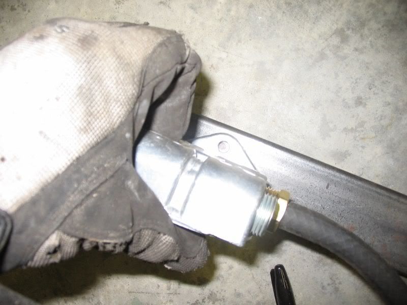
2. Assemble the check valve assembly by attaching the 3/8” NPT female to barb on each end. Use the 9/16” wrench and hold the check valve and use a 5/8” wrench to tighten down the barb fittings. Go ahead and use thread sealant on the PUMP side of the fitting. The fitting is marked with an arrow in which the direction of the fuel flows. The PUMP side is the side which does not have the adjusting nut. The setup looks like this:
http://i198.photobucket.com/albums/aa222/8mpg_walbro/Plumbing/002.jpg
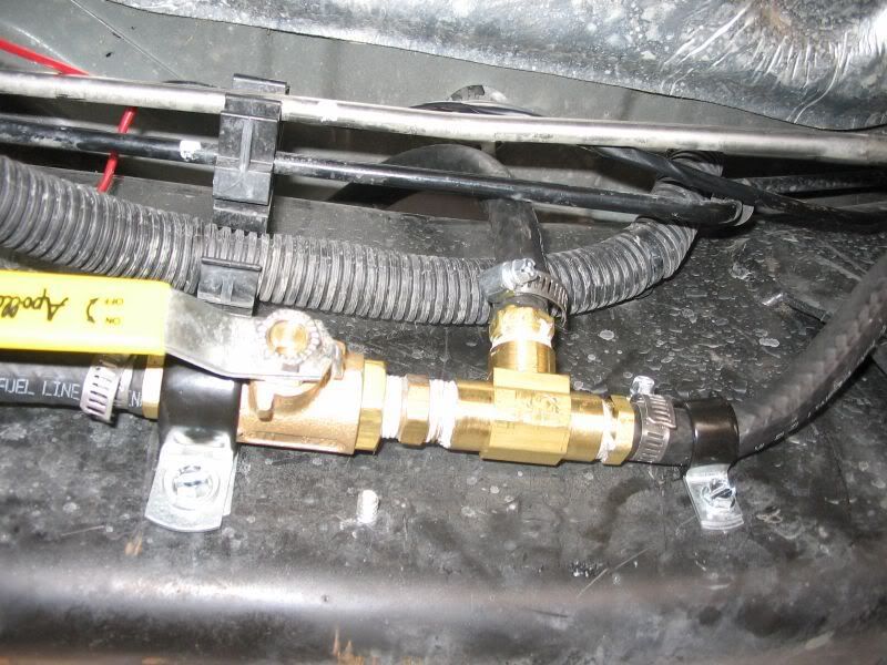
3. Assemble the ball valve and the female “T” fitting using the (3) 3/8” NPT Male to 3/8” Barb fittings and the 3/8” NPT male union. Use thread sealant on all threaded ends when assembling. Use the 7/8” wrench to hold the ball valve and a 5/8” wrench to attach the barb and union. Keep in mind which way the valve handle faces when in the off position. With the handle turned off, (handle facing up), you want the ball valve to be on the LEFT and the female “T” on the right. Use the 11/16” wrench to hold the female “T” and attach the barb fittings and union as pictured below. Using the large P clamp, slide the clamps over the ball valve as pictured.
http://i198.photobucket.com/albums/aa222/8mpg_walbro/Plumbing/003.jpg
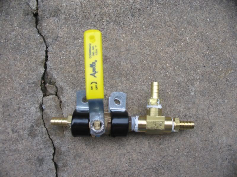
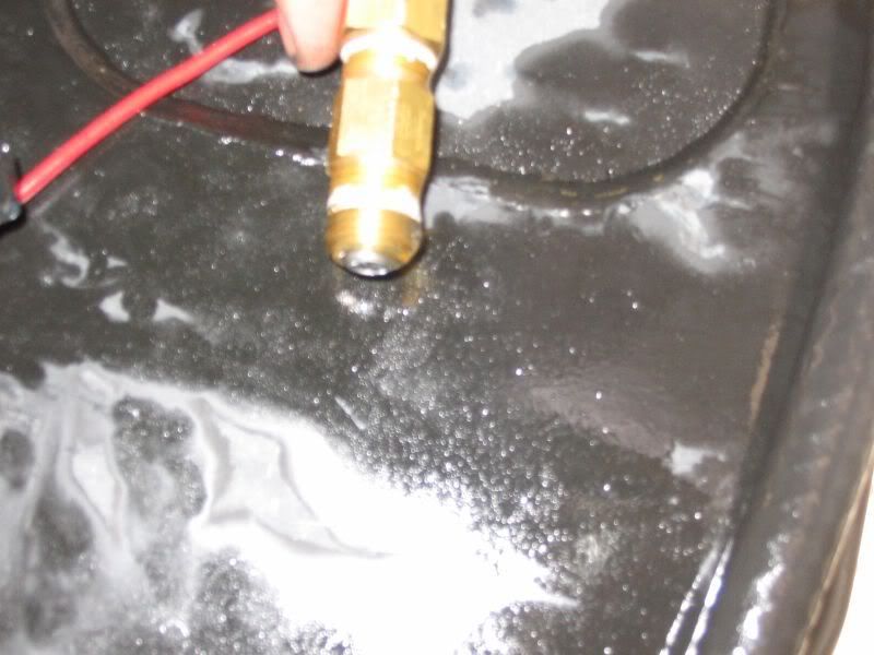
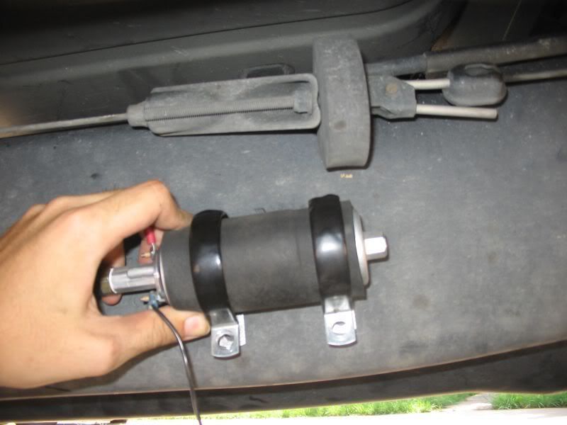
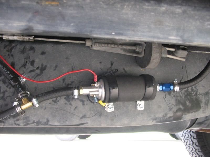
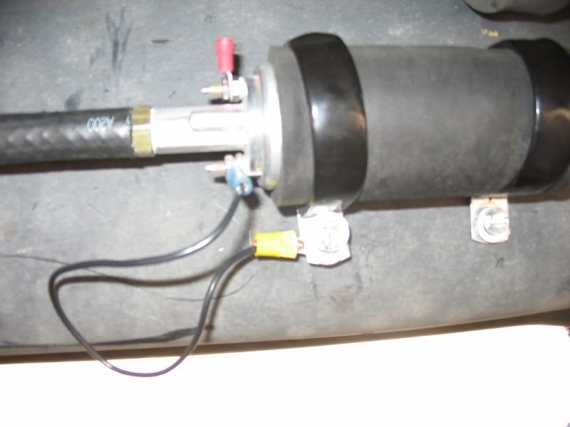
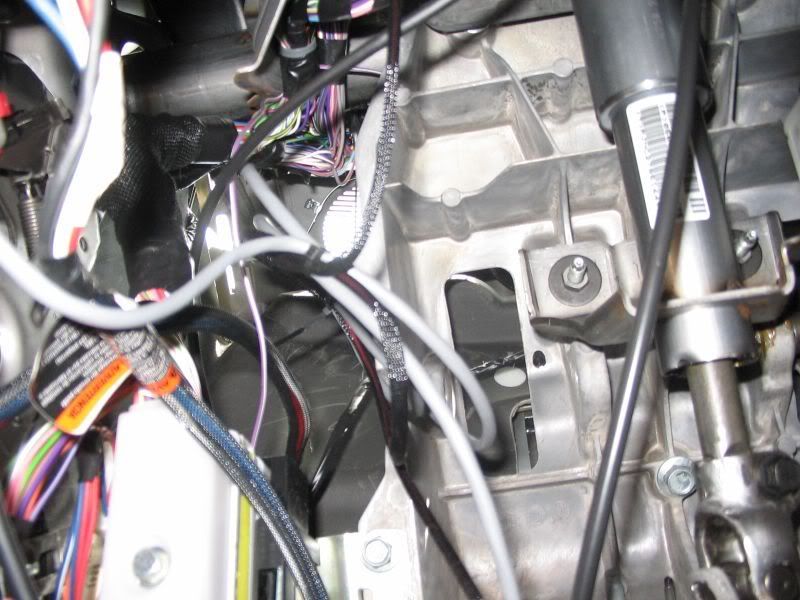
4. Attach the 10mm to 3/8” barb fittings onto the pump using 5/8” wrench and hold the pump with your other hand. You can use a wrench on the hexagonal legs off the pump. Use thread sealant on the 10mm threaded side. Cover the pump with the supplied foam and attach the P shaped rubber clamps. It is time to mount the pump. Hold the pump up to the area where you want to mount it. Using the sharpie, mark the locations to drill the holes. The fuel pump is mounted on the outside frame rail.
http://i198.photobucket.com/albums/aa222/8mpg_walbro/Plumbing/004.jpg
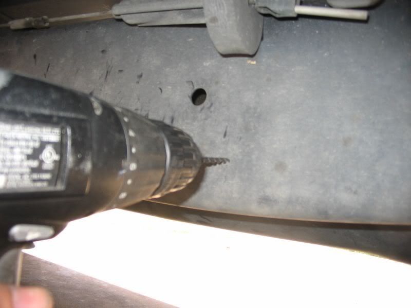
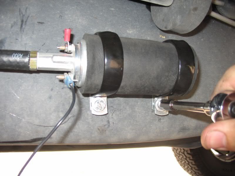
5. Drill the holes using an 3/16” drill bit. Using the 5/16” flat washer and #12x1 screws, attach the pump to the drilled holes. Use the ¼” ratchet, extension and 3/16” socket to tighten down the machine screws. On the front side, put the large ring terminal under the washer and through the screw and tighten it down.
http://i198.photobucket.com/albums/aa222/8mpg_walbro/Plumbing/005.jpg
http://i198.photobucket.com/albums/aa222/8mpg_walbro/Plumbing/006.jpg
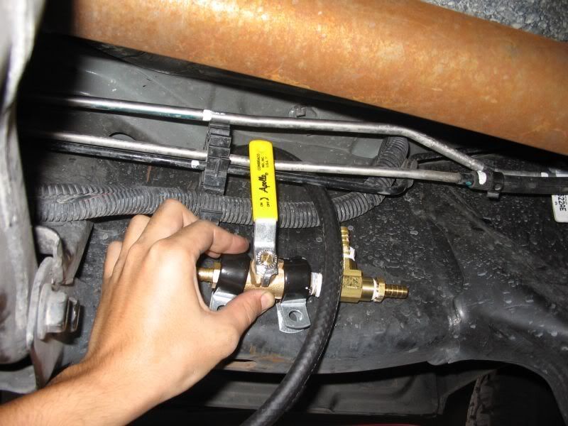
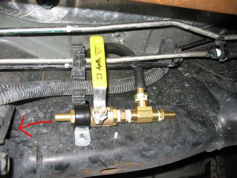
6. Time to mount the ball valve. The ball valve is mounted on the INSIDE of the drivers side frame rail, just forward of the transmission crossmember. Make sure the back side (left in the pictures below) barb is aiming into the triangle shaped pass-through between the crossmember braces. Mark, drill the holes and use the flat washers and machine screws and mount the ball valve. I intended to use 2 clamps on the ball valve but I snapped off the head of the screw…don’t do that.
http://i198.photobucket.com/albums/aa222/8mpg_walbro/Plumbing/007.jpg
http://i198.photobucket.com/albums/aa222/8mpg_walbro/Plumbing/008.jpg
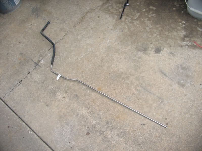
7. Pull the larger (upper)(supply) fuel line out of the bracket near the transfer case as well as the one just forward of the crossmember (near the ball valve as pictured above). You are going to cut the stock supply line near the front of the fuel tank. Using the mini tubing cutter, cut the supply hard line just behind the mounting bracket as pictured below. If you have never used a tubing cutter, it is easy. Simply straddle the tube with the cutter. The tubing should be placed between the upper two rollers and the large sharp wheel will cut the tube. Tighten the clamp finger tight and then just a bit. The idea is not to crush the tube but put enough pressure on it to cut. Twirl the cutter 2-3 times and tighten the adjustment knob just a bit more and twirl again. Keep going until the fuel line is cut. Fuel will leak out of the fitting as it is getting thinner and thinner so a bucket to catch the fuel comes in handy.
http://i198.photobucket.com/albums/aa222/8mpg_walbro/Plumbing/009.jpg
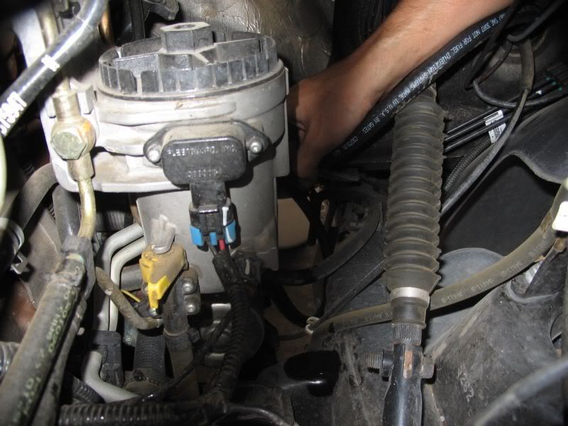
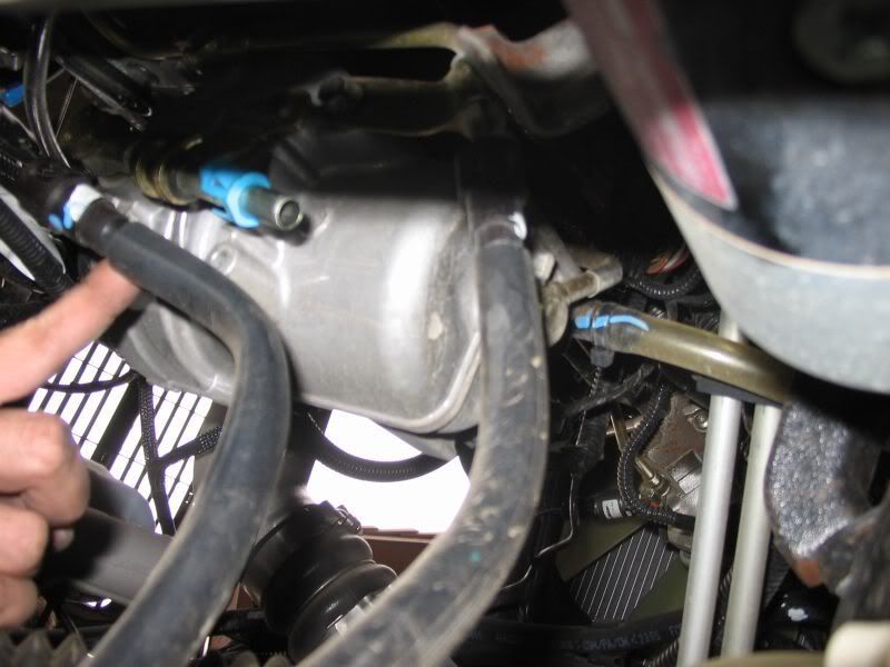
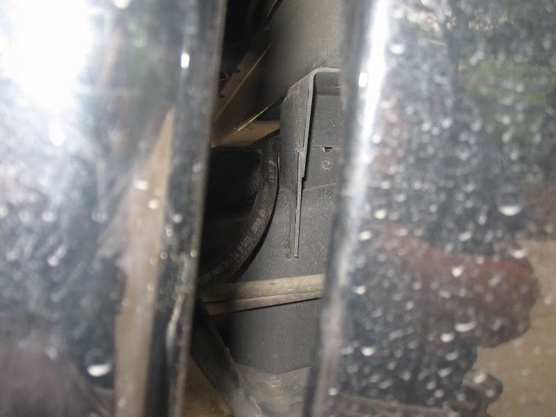
8. Disconnect the supply line at the other end of the line. The line changes into a plastic line with a rubber hose on the outside. At the end is a dorman
connector attached to the fuel filter housing. Push the two clips at the very end of the fitting towards the center and pull down on the fitting itself. You are not pulling the plastic insert off with the actual connector. Look at your new connector and you will understand. You can reach it by standing on the bumper and reaching behind the fuel filter housing or if you have a skinny arm, you can approach it from the side and wedge your arm behind the battery and by the brake hoses. When disconnected, pull the stock fuel line out from the engine bay.
http://i198.photobucket.com/albums/aa222/8mpg_walbro/Plumbing/010.jpg
http://i198.photobucket.com/albums/aa222/8mpg_walbro/Plumbing/011.jpg
http://i198.photobucket.com/albums/aa222/8mpg_walbro/Plumbing/012.jpg
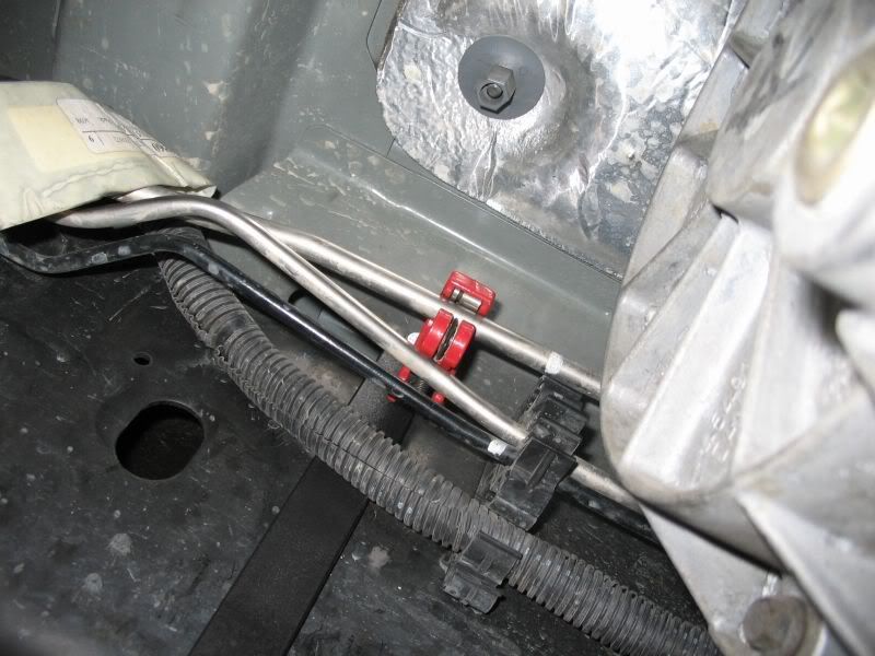
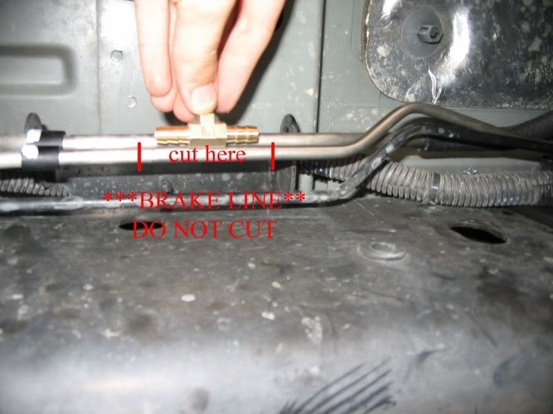
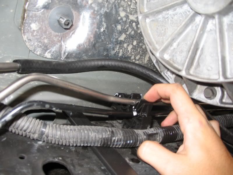
9. Using the 5/16” “T” fitting, hold it up to the return line (smaller lower silver line) (DO NOT CUT THE BLACK HARD LINE…IT’S THE BRAKE LINE). Mark the fitting ¼” on each side of the fitting. Move what is left of the stock fuel SUPPLY line up over the bracket above so its not in the way to make the cut. Using the tube cutter, cut out the marked section as pictured below.
http://i198.photobucket.com/albums/aa222/8mpg_walbro/Plumbing/013.jpg
http://i198.photobucket.com/albums/aa222/8mpg_walbro/Plumbing/014.jpg
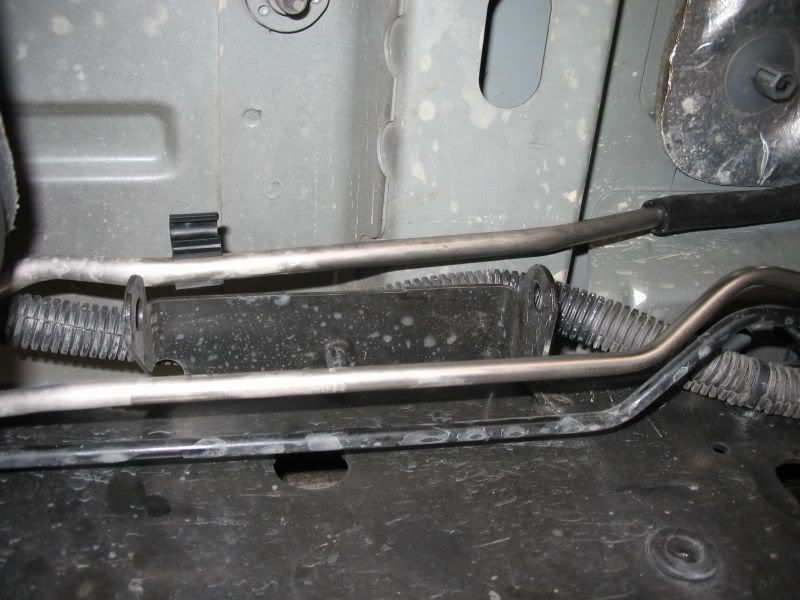
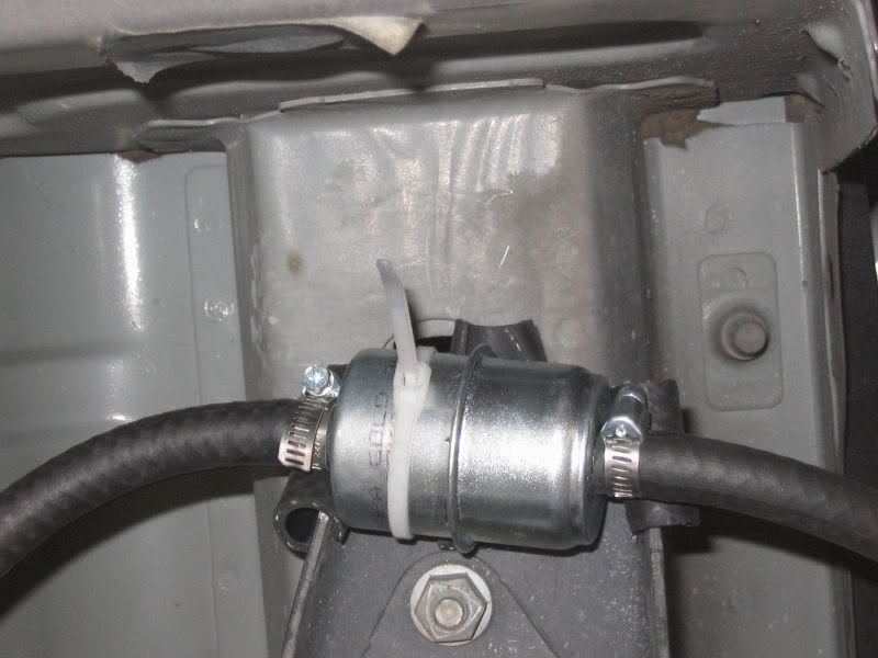
10. Get the barbed pre filter and get it ready to be mounted. Using 2” strips of the 3/8” fuel line (or the 5/16” if you had to buy 1’ of it) cut it down the middle with dikes or a razor blade. You will need 3 pieces cut like this. On the rear cab body mount, cover the sharp edges of the metal. Using the filter and zip ties, zip tie the filter to the two holes in the mount. Wedge the third piece of rubber between the bottom of the mount and the top of the filter. This will insulate it and keep it from vibrating. This mount is located to the rear of the fuel pump. Use 2 zip ties (I only had 1 at the time)
http://i198.photobucket.com/albums/aa222/8mpg_walbro/Plumbing/015.jpg
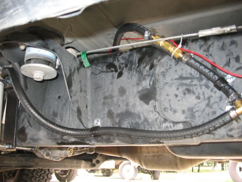
11. Time to start running all the rubber hose. Starting from the tank, pull the line coming off the new fuel pickup in the tank towards the pump. Pull the hose under the front (first) crossmember for the bed and down to the outside of the frame rail.
http://i198.photobucket.com/albums/aa222/8mpg_walbro/Plumbing/016.jpg
12. Route the hose toward the rear body mount and cut it to length (a little slack is ok). Connect it to the rear side of the prefilter use a hose clamp and tighten. On the front side, attach another piece of hose with a clamp and route it towards the back side of the fuel pump. Cut and attach with the hose clamp. (I was missing a 10mm to barb so I had to use some –AN fittings)
http://i198.photobucket.com/albums/aa222/8mpg_walbro/Plumbing/017.jpg
http://i198.photobucket.com/albums/aa222/8mpg_walbro/Plumbing/018.jpg
13. Attach a short piece of hose (4-5”) to the front of the pump and secure with a clamp. Attach the other end to the 3/8” barbed “T” fitting again using a hose clamp. The top the “T” fitting goes to the check valve and the front part goes to the fuel filters. Attach a hose from the front port of the “T” and connect it to the “IN” side of the rear filter. Use hose clamps on both ends. Be sure to leave enough slack to route the hose as pictured and try not to kink the hose. Also attach a 3-4” piece of hose to the top port of the “T” and attach the check valve. Make sure you look for the direction of flow of the check valve. The sealed end goes towards the pump. The arrow is also another indicator, and it points towards the floor of the truck (up). Again, using hose clamps, secure the hoses. (The top hose is a bit to long in my picture. A 3-4” piece should be perfect.)
http://i198.photobucket.com/albums/aa222/8mpg_walbro/Plumbing/019.jpg
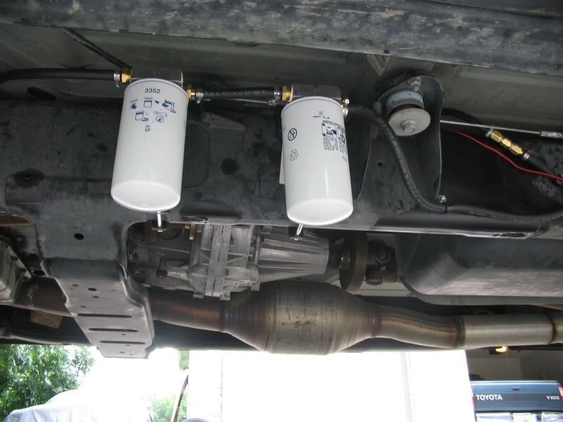
14. Attach a piece of hose between the 2 auxiliary fuel filters and secure with a clamp. Attach another piece of hose to the front of the forward fuel filter and route it over the frame rail to the female “T” fitting attached to the ball valve. Cut it to length and attach it to the top port of the “T” securing it with clamps.
http://i198.photobucket.com/albums/aa222/8mpg_walbro/Plumbing/020.jpg
http://i198.photobucket.com/albums/aa222/8mpg_walbro/Plumbing/021.jpg
15. Using 3/8” hose, route the hose through the triangle section of the crossmember by the ball valve and route it towards the stock hard supply fuel line. Put a hose clamp over the hard line and push the rubber line on 2-3”. Tighten down the clamp. Cut and attach the other end of the hose to the rear port of the ball valve pictured below.
http://i198.photobucket.com/albums/aa222/8mpg_walbro/Plumbing/022.jpg
http://i198.photobucket.com/albums/aa222/8mpg_walbro/Plumbing/023.jpg
16. Estimate the length of hose from the front side of the female “T” to where the dorman connector attaches to the fuel filter housing. Remove the plastic insert from the new dorman connector. Connect the dorman fitting to one end and secure with a hose clamp. Connect the dorman connector to the fuel filter housing and make sure you hear the insert make a clicking sound when it locks. Route the hose as the stock hose was and push the hose into the stock bracket at the top of the frame rail at the rear of the engine bay. Route the hose back and connect it to the front of the female “T” fitting and secure with a hose clamp
http://i198.photobucket.com/albums/aa222/8mpg_walbro/Plumbing/024.jpg
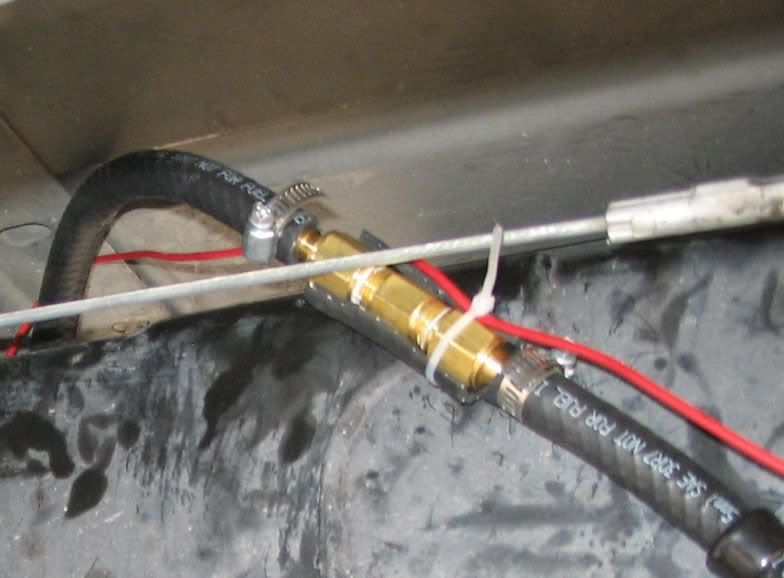
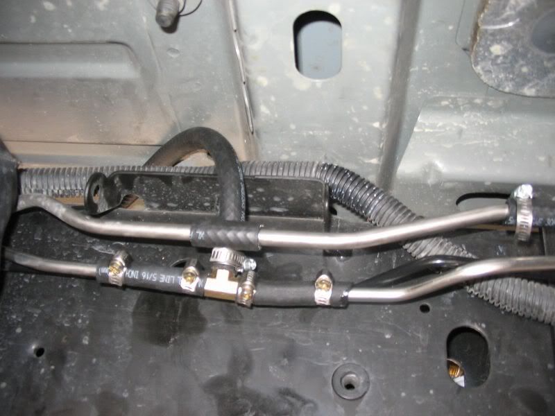
17. Using the 5/16” fuel line, cut two 3” sections. Connect each end onto the stock 5/16” return line. Connect both end to the 5/16” “T” fitting and secure with clamps. The hose should be pushed about 2” onto the stock fuel line and secure the barbed and hard line ends with hose clamps. Using a 3/8” hose, connect to the output side of the check valve and secure it with a hose clamp. The is the side in which the arrow is pointing (also has the adjustment nuts in it). Loop the hose over the frame rail and attach it to the 5/16” barbed “T” fitting. Tighten the hose clamp on the top of the 5/16” T.
http://i198.photobucket.com/albums/aa222/8mpg_walbro/Plumbing/025.jpg
http://i198.photobucket.com/albums/aa222/8mpg_walbro/Plumbing/026.jpg
18. All of the fuel lines should now be connected. Using the small hose clamps, mount clamps as pictured above to secure the hose to the frame rail. Use the 3/16” drill bit and #12 screws just like when mounting the pump and ball valve. Also mount one forward of the ball valve as pictured below. If you feel that more hose clamps are needed to secure the hose, more clamps shouldn’t hurt anything.
http://i198.photobucket.com/albums/aa222/8mpg_walbro/Plumbing/027.jpg
19. Close the ball valve so that the handle is facing up. This will keep the walbro pump from pumping the fuel back into the stock lift pump line.
Time to wire the pump.
Wiring the Fuel Pump
Tools Needed:
Drill
¼” drill bit
Crimpers
Dikes
Wire strippers
½” wrench
Razorblade
Electrical tape
10mm socket
3/8” ratchet
Parts Needed:
Relay
Female spade terminals (4)
20’ 16ga wire
Inline fuse holder and 20amp fuse (1 ea)
Large Ring terminals (2)
Small Ring terminal (1)
Female and male weatherproof bullet connector (1 ea)
¼” x 1” bolt (1)
¼” lock washer (1)
¼” nut (1)
Small zip ties
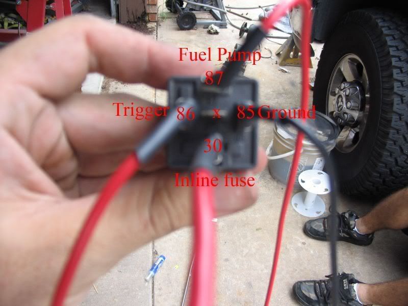
1. Cut a section of wire 8” long. This will be your ground wire. It does not have to be black but black is a common ground color. Strip ¼” of shielding off both end. Crimp a female spade terminal one one and a ring terminal on the other using the crimpers. Connect the spade terminal to pin #85. Cut a section of wire 4’ (feet) long and strip ¼” of shielding on one end. Attach and spade terminal to this end. Connect it to pin #86. This is your trigger wire and will feed off the stock fuel pump wire. Using the inline fuse, attach a ring terminal at one end and a spade at the other. Attach the spade terminal of the inline fuse to pin#30. This is your hot source and the other side will attach to the battery positive terminal in a bit. With the remaining wire, strip the shielding ¼” back and attach a spade terminal. Plug this wire into pin #87. This wire will feed power to the pump
http://i198.photobucket.com/albums/aa222/8mpg_walbro/Wiring/001-1.jpg
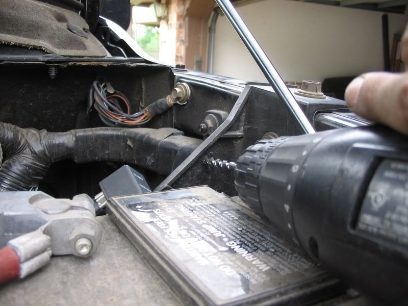
2. Using the drill and ¼” bit, drill the back side of the drivers battery box near the top to mound the relay. Mount the relay using the ¼” x 1” bolt, lock washer and nut.
http://i198.photobucket.com/albums/aa222/8mpg_walbro/Wiring/002-1.jpg
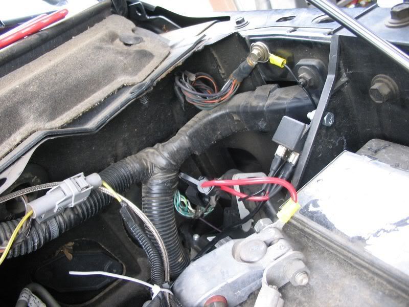
3. Connect the ring terminal on the inline fuse to the battery positive (+) terminal. Be careful not to touch metal when pulling the nut off or putting it on. Use the ½” wrench to pull off the rear side nut. Slide on the ring terminal and reattach the nut. Using a 10mm socket, disconnect the ground bolt located on the inside, top, rear drivers fender. Connect the ground wire ring terminal to the existing ground wire and place the bolt back through and retighten the nut.
http://i198.photobucket.com/albums/aa222/8mpg_walbro/Wiring/003-1.jpg
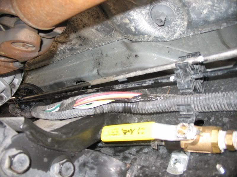
4. Route the two long wires down under the wiring harness along the firewall and down by the brake lines. Route them down following the new fuel supply line
towards the convoluted tubing. Just forward of the transmission crossmember pull the wiring harness out of the protective tubing. And locate the fuel pump positive wire (orange with red tracer). Pull this wire out a bit just to separate it from the rest
http://i198.photobucket.com/albums/aa222/8mpg_walbro/Wiring/004-1.jpg
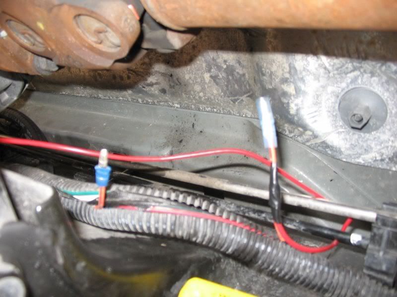
5. Cut the fuel pump wire. Strip ¼” of the shielding on rear side of the new cut wire. On the rear part, crimp the MALE side of the bullet connector onto it. Trim ½” of the shielding on the front side of the cut wire. Pull your trigger wire towards the front side of the cut wire. Route the wire nicely along the top of the frame rail using the fuel line bracket to hold the wire. Route the wire between the frame rail and the fuel lines. Cut the shielding ½” back. Twist the front half of the stock fuel pump wire with the trigger wire from the relay. Attach the female portion of the bullet connector and crimp them together. I suggest electrical taping the connector and the wires together. Tuck the wiring harness and both bullet connectors into the protective tubing. Do NOT connect the bullet connectors. Only connect them if the walbro dies and you need to get the stock pump working to get home
http://i198.photobucket.com/albums/aa222/8mpg_walbro/Wiring/005-1.jpg
6. Route the long power wire to towards the fuel pump. Tuck the wire into the tubing the best you can and follow the tubing path towards the rear. When you are near the fuel pump, pull the wire out and loop it over the frame rail. Attach the end of the wire to the fuel pump positive (+) with the small ring terminal. Tighten down the nut that secures the terminal. Secure both the trigger wire and power wire with zip ties as needed
http://i198.photobucket.com/albums/aa222/8mpg_walbro/Wiring/006-1.jpg
http://i198.photobucket.com/albums/aa222/8mpg_walbro/Wiring/007-1.jpg
7. Using a small 3-4” section of wire, strip both ends 1/4”. Crimp a small ring terminal on one end and a larger one on the other. Attach the small side to the pump negative (-). The large side will go under the washer holding the front fuel pump clamp. Using the 3/16” socket and wrench, loosen the screw. Put the large ring terminal between the clamp and the washer. Retighten the screw.
http://i198.photobucket.com/albums/aa222/8mpg_walbro/Wiring/008-1.jpg
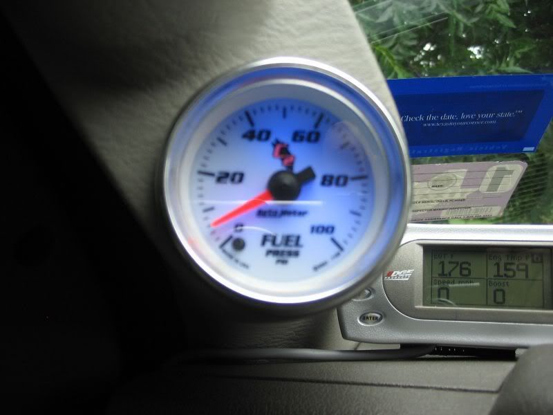
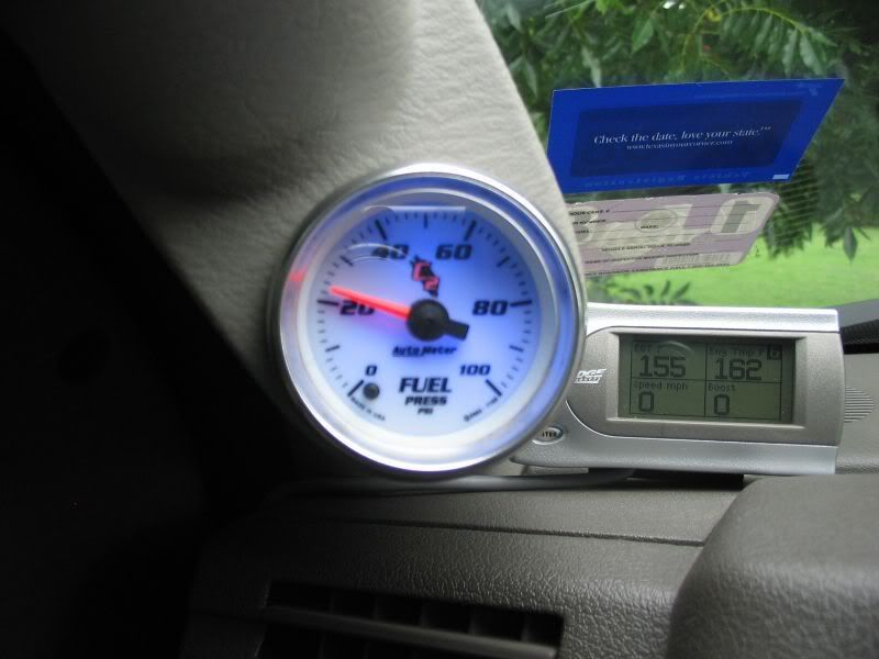
8. The fuel system should be ready to fire. Insert the 20a fuse into the fuse holder. Insert the key into the ignition and click it to the run position. The fuel pressure gauge should slowly kick up. The pump has to fuel the new filters, the filter housing on the block before you will see pressure. Keep a close eye on the pressure!! If it goes over 20, pull the key out of the ignition. This is where tuning the check valve gets fun. Disconnect the top barb fitting and use the 3mm allan wrench and loosen the lock nut. Turn the adjusting nut counter clockwise to loose spring tension. Watch out, fuel will spill…the bucket comes in handy again. Plug it all back up and retry the ignition and check for pressure. If it is to high again, do the same adjustment. If too low, turn the adjustment nut clockwise. Adjust the fuel pressure until it rests near 20 with the pump on. As a note, the computer sends a signal to the stock lift pump wire and runs the pump to prime it for a couple seconds. The fuel pump will kick on and then stop pumping because its just trying to prime the motor. You may have to start the motor to get the fuel pressures. If you have a friend, turn the key to the “on” position and disconnect the pin #87 on the relay. Have a friend hold the spade terminal to the positive terminal on the battery. This will make the fuel pump stay on so you can get the fuel pressure readings without starting the truck. Adjust until you get the right pressure and then re-attach the spade terminal to #87 on the relay. Once you have the pressure set, tighten down the lock nut on the check valve. Using thread sealant, put it on the threads and tighten down the barb fitting one last time. Connect the fuel line and tighten the clamp.
9. When starting the vehicle you will see the gauge jump up to 20psi or whatever you set it at and slowly fall back down to 2-4psi. This was the computer telling the fuel pump to prime. You can safely start the truck. The gauge will then raise back up to the pressure setting you set.
http://i198.photobucket.com/albums/aa222/8mpg_walbro/Wiring/009-1.jpg
10. Look under the truck for any leaks. If a hose is leaking at the barb, tighten the hose clamp. If a brass fitting is leaking, tighten the fitting. Make sure you used thread sealant on all the threaded brass fittings. Let the truck idle and double and triple check for leaks. Take the truck for a test drive and see how she does. Address any leaks. If for some reason the Walbro pump dies, just simply open the ball valve, pull the bullet connectors out of the loom and connect them. This will let the power flow back to the stock lift pump and the pump will be able to function as it used to.
http://i198.photobucket.com/albums/aa222/8mpg_walbro/Wiring/010-1.jpg
That’s it… Hope this write up helps… Any questions should be posted in the thread that you found this write up in.
Electric Fuel Pressure Gauge Install
Tools:
17mm socket wrench
3/8” ratchet
Drill press
1/8” drill bit
5/16” drill bit
1/8 NPT tap and handle
Test light
Small flat blade screw driver
10mm deep socket (or 10mm socket +3” extension)
Razor blade
Electrical Tape
Vice
Vice Grips
WD40 or cutting oil
Thread sealant
Crimpers
Ring terminal
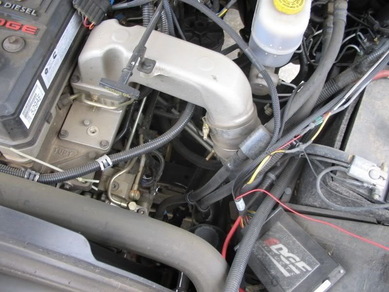
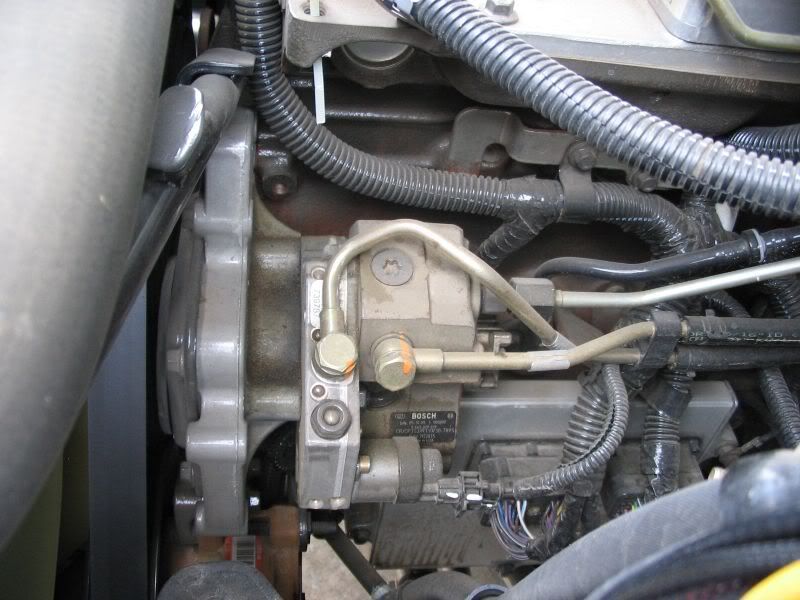
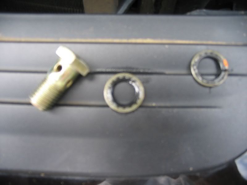
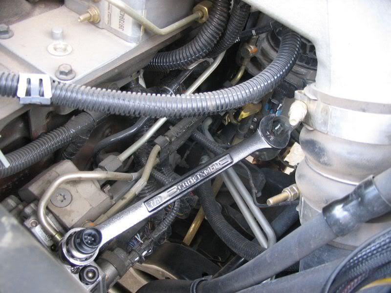
1. Open the hood and locate the cp3. Remove the front towards the front of the truck on the cp3. They are banjo fittings and have hollow centers. When you remove the bolt, make sure you do not lose the washers… There are 2 washers, one on the top of the eyelet and one on the bottom.
http://i198.photobucket.com/albums/aa222/8mpg_walbro/Fuel%20Pressure%20Gauge/001.jpg
http://i198.photobucket.com/albums/aa222/8mpg_walbro/Fuel%20Pressure%20Gauge/003.jpg
http://i198.photobucket.com/albums/aa222/8mpg_walbro/Fuel%20Pressure%20Gauge/004.jpg
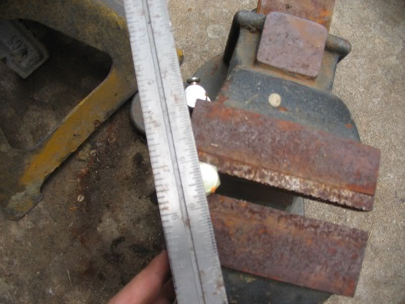
2. Place the bolt in the vice. Don’t clamp down on it to hard, you just need the vice to hold it still. Using a ruler or strait edge and razor blade, mark the bold from corner to opposite corner. You are referencing the center point of the bolt.
http://i198.photobucket.com/albums/aa222/8mpg_walbro/Fuel%20Pressure%20Gauge/006.jpg
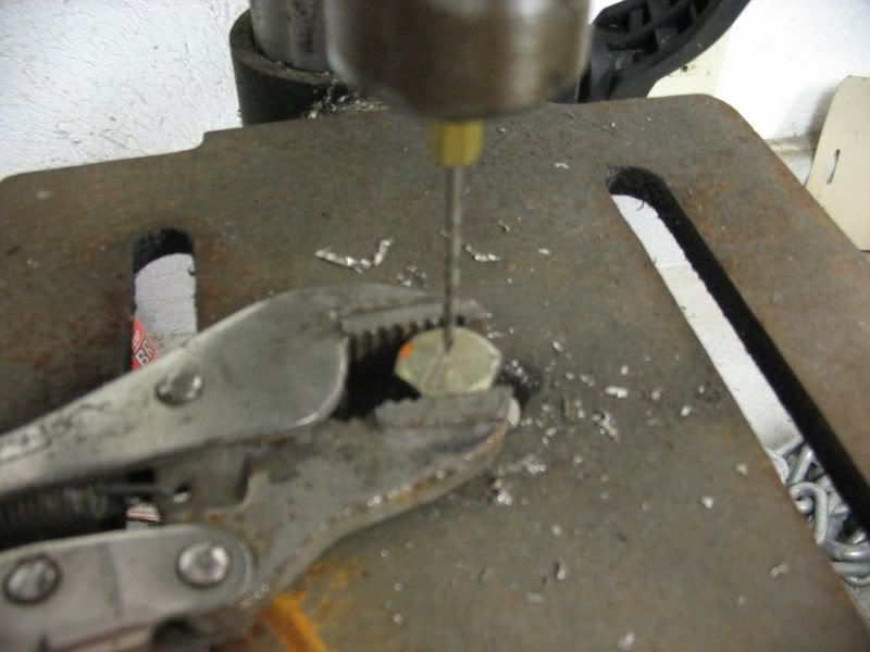
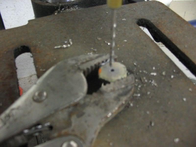
3. Take a pair of vice grips and adjust it to hold the head of the bolt firmly. Now using the 1/8” drill bit on the drill press (cordless drill will work with the vice), drill the center of the bolt until you push all the way through.
http://i198.photobucket.com/albums/aa222/8mpg_walbro/Fuel%20Pressure%20Gauge/008.jpg
http://i198.photobucket.com/albums/aa222/8mpg_walbro/Fuel%20Pressure%20Gauge/010.jpg
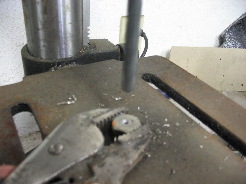
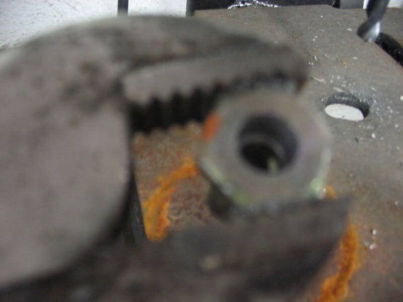
4. Now drill out the bolt with the 5/16” drill bit. You are trying to push through the head only. Do not continue to drill until you reach the bottom of the bolt. The inside diameter of the banjo bolt is less than 5/16” Drill through the head only. If you need to, use a measuring tape and measure the thickness of the head and tape off your drill bit at that depth.
http://i198.photobucket.com/albums/aa222/8mpg_walbro/Fuel%20Pressure%20Gauge/011.jpg
http://i198.photobucket.com/albums/aa222/8mpg_walbro/Fuel%20Pressure%20Gauge/012.jpg
http://i198.photobucket.com/albums/aa222/8mpg_walbro/Fuel%20Pressure%20Gauge/012.jpg
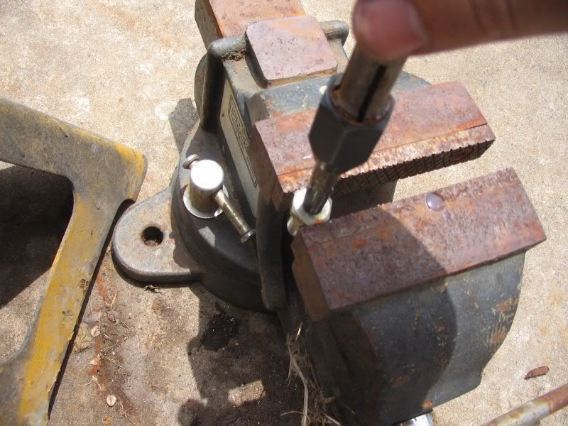
5. Place the bolt in the vice again using the vice to clamp onto the hex sides of the bolt. Using the 1/8” NPT tap, start tapping the bolt. Try and keep the tap vertical and tap the bolt straight in the hole. Use the cutting oil or WD40 to lube the tap. If you have not used a tap before, start the tap slowly. When you get a couple turns in, turn the tap counter-clockwise to clear up the threading. Then start in a clockwise turn again. You want to tap the bolt at least 3/4 of the bolt head.
http://i198.photobucket.com/albums/aa222/8mpg_walbro/Fuel%20Pressure%20Gauge/014.jpg
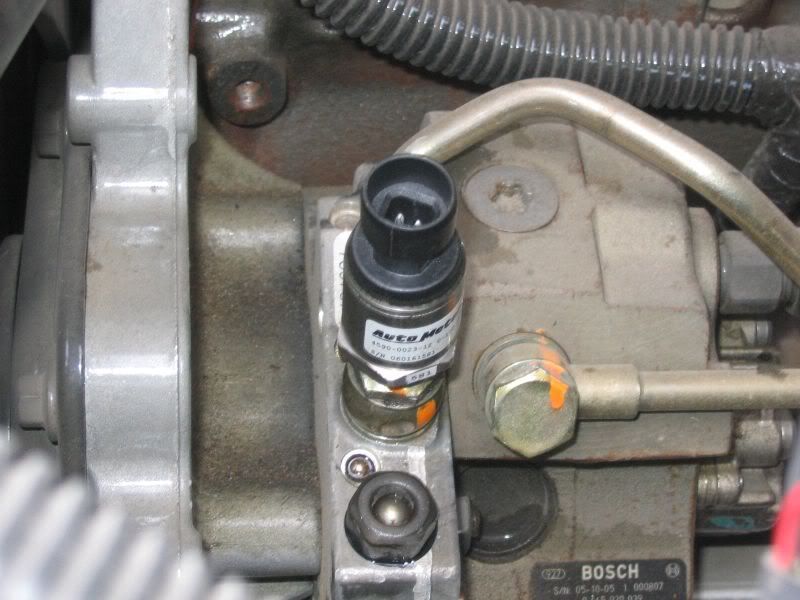
6. When finished tapping, make sure you clean out the bolt really well. If you have an air compressor, go ahead and blow out the fitting. You don’t want any loose fragments of metal or shavings to go into the cp3. When you decided it is ready, to ahead and reinstall the bolt into the cp3. Make sure you put a washer between the cp3 and the eyelet part of the banjo, and the other between the eyelet and the bolt head. Tighten down the bolt. You do not have to tighten the bolt like you are the hulk, just a good hand tight is fine. Don’t over tighten the bolt. Apply thread sealant to the pressure sender threading. Thread the fuel pressure sender and tighten using a 7/8” wrench. Again, don’t act like you are the hulk. The thread sealant will keep it from leaking…you don’t want to overtighten
and snap off the sender.
http://i198.photobucket.com/albums/aa222/8mpg_walbro/Fuel%20Pressure%20Gauge/015.jpg
http://i198.photobucket.com/albums/aa222/8mpg_walbro/Fuel%20Pressure%20Gauge/016.jpg
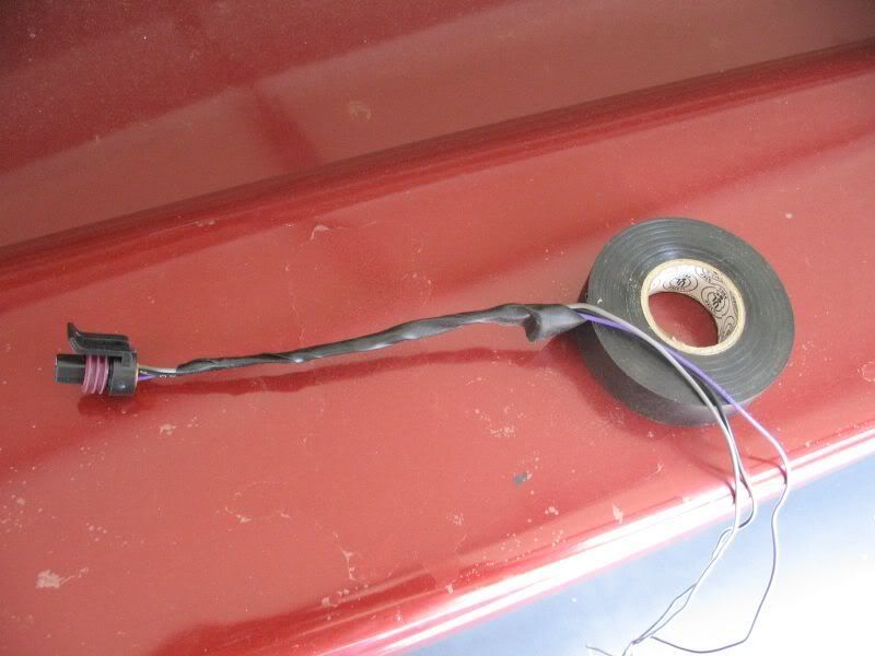
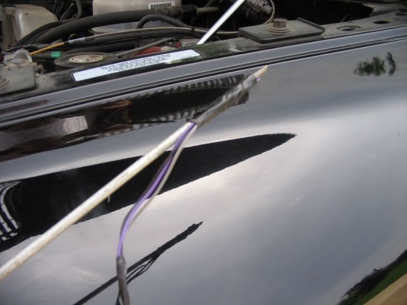
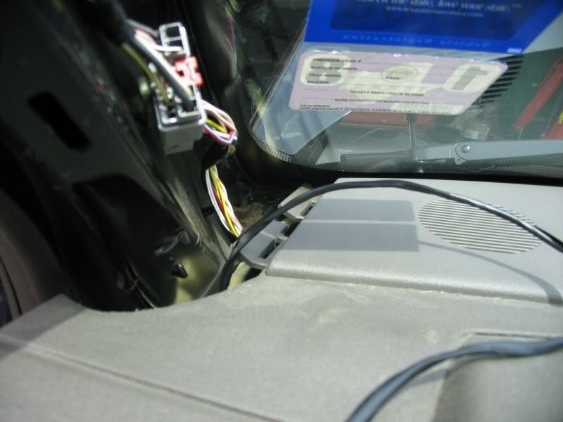
7. Electrical tape the wiring harness together making for a clean installation. Clip on the supplied wiring harness to the sending unit. Find a way to route the wiring away from any heat source and out of the way. I route mine on a couple of existing wiring harnesses and back towards the firewall. Using the razorblade, fine a rubber grommet that you want to poke the harness through and make a small cut large enough to fit the harness end through. Tape the gauge end of the wiring harness to the end of the flat blade screwdriver and push it through the cut you made in the grommet
http://i198.photobucket.com/albums/aa222/8mpg_walbro/Fuel%20Pressure%20Gauge/017.jpg
http://i198.photobucket.com/albums/aa222/8mpg_walbro/Fuel%20Pressure%20Gauge/019.jpg
http://i198.photobucket.com/albums/aa222/8mpg_walbro/Fuel%20Pressure%20Gauge/021.jpg
8. Go inside the truck and un-tape the harness from the screw driver and pull the screwdriver out
http://i198.photobucket.com/albums/aa222/8mpg_walbro/Fuel%20Pressure%20Gauge/021.jpg
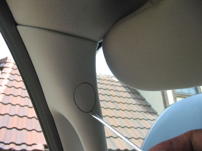
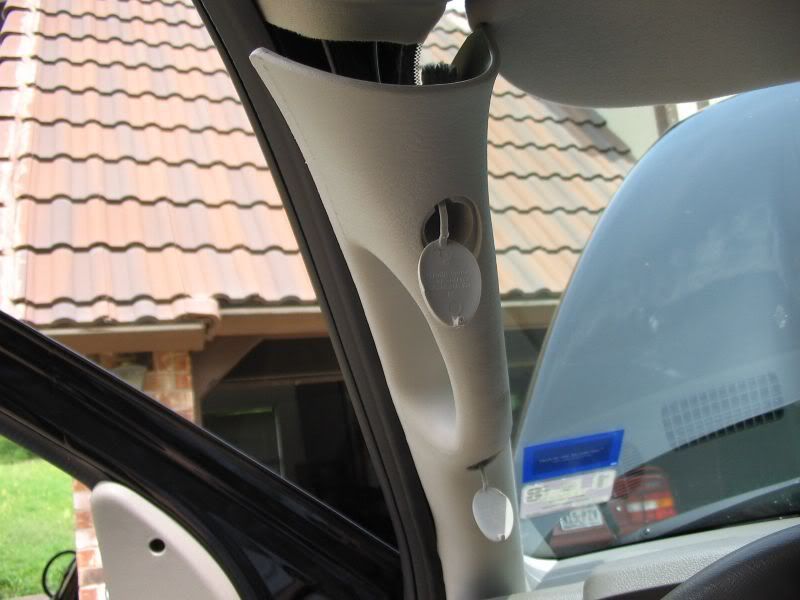
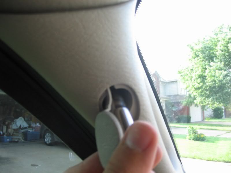
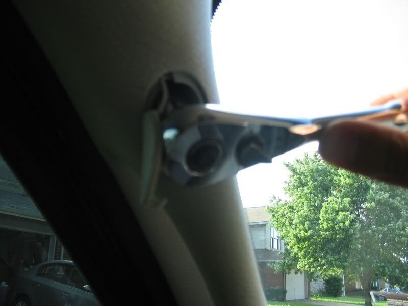
9. Get the small flat blade screw driver and pop out the bolt covers in the drivers side pillar. You want to pry from the bottom of the top cover and the top of the bottom cover. Using the socket wrench and 10mm socket, remove the two bolts holding the pillar on.
http://i198.photobucket.com/albums/aa222/8mpg_walbro/Fuel%20Pressure%20Gauge/023.jpg
http://i198.photobucket.com/albums/aa222/8mpg_walbro/Fuel%20Pressure%20Gauge/024.jpg
http://i198.photobucket.com/albums/aa222/8mpg_walbro/Fuel%20Pressure%20Gauge/025.jpg
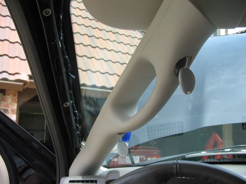
Using the grab handle, pull the top of the pillar down. Then pull the pillar toward the center of the truck. There are 2 taps connecting it at the bottom where the pillar and dash meet. DON’T YANK AT IT OR YOU WILL BREAK THEM. Grab the bottom and pull up to pull the tabs out.
http://i198.photobucket.com/albums/aa222/8mpg_walbro/Fuel%20Pressure%20Gauge/027.jpg
http://i198.photobucket.com/albums/aa222/8mpg_walbro/Fuel%20Pressure%20Gauge/028.jpg
http://i198.photobucket.com/albums/aa222/8mpg_walbro/Fuel%20Pressure%20Gauge/029.jpg
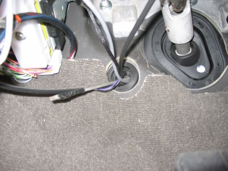
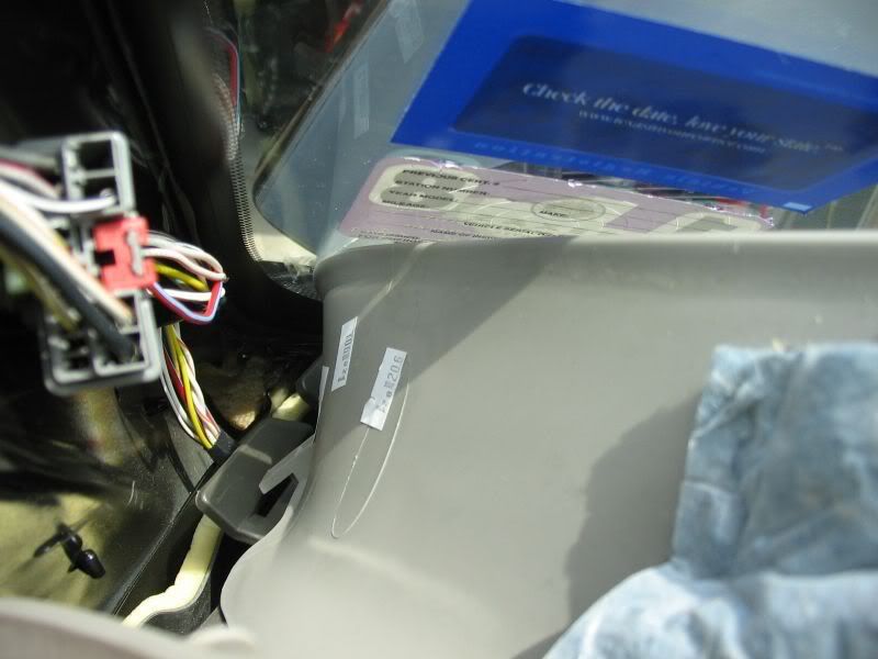
11. Stick your head under the dash and look up. You should see sunshine where the pillar used to be. This is where you will route the end of the wiring harness up through. With one hand under the dash and one hand on top, feed the wire up and into the hole and grab it from up top. Pull the wire so it doesn’t accidentally feed back down.
http://i198.photobucket.com/albums/aa222/8mpg_walbro/Fuel%20Pressure%20Gauge/030.jpg
http://i198.photobucket.com/albums/aa222/8mpg_walbro/Fuel%20Pressure%20Gauge/031.jpg
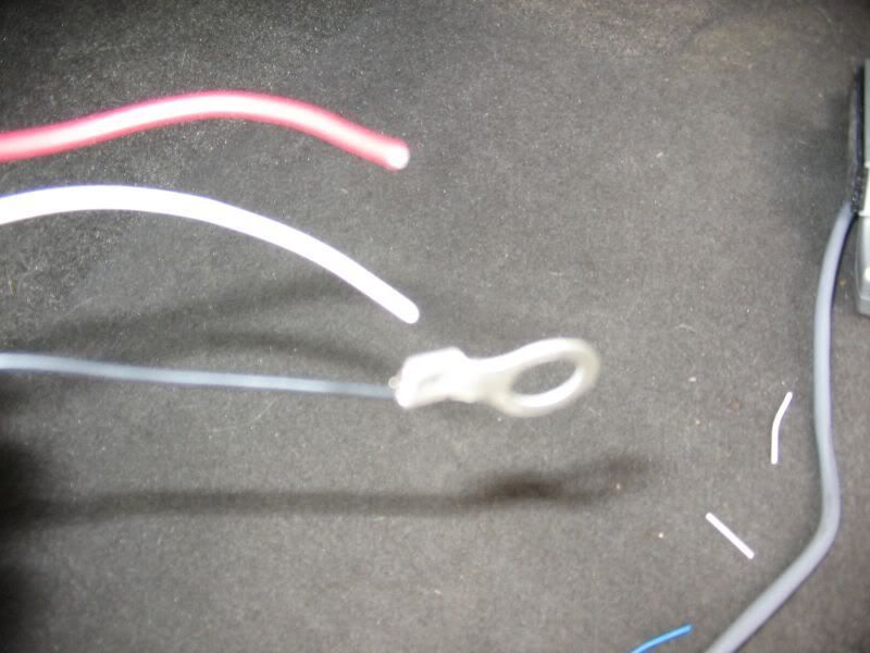
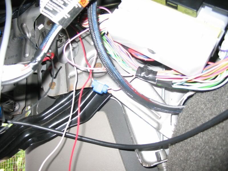
12. Crimp a ring terminal on the end of the black wire that has no end. This is your ground. Connect it to any bolt or screw that touches metal. I used the screw off the hood latch. Locate the PINK/Purple tracer wire. This is a switched hot source. It is located on the main wiring harness with the white cover. Use your test light and verify it’s a switched hot source. You can ground the test light on the metal on the dash around the hood latch. To verify, poke the wire with the key off and you should have no light. When you switch the key on, the test light will turn on. This is a switched hot. You can use a wire tap if you have one but you don’t have to. If you don’t have one, using the razor blade, cut back about ½” of shielding. Use the test light, poke a hole through the center of the copper wiring. Take the red wire from the gauge and strip the end about ½” With the end stripped, twist the wire together and insert it through the hole you made in the wiring. After putting it through the wiring, twist the red wire around the pink and tape the harness so the wires are no longer exposed.
http://i198.photobucket.com/albums/aa222/8mpg_walbro/Fuel%20Pressure%20Gauge/032.jpg
http://i198.photobucket.com/albums/aa222/8mpg_walbro/Fuel%20Pressure%20Gauge/033.jpg
http://i198.photobucket.com/albums/aa222/8mpg_walbro/Fuel%20Pressure%20Gauge/034.jpg
http://i198.photobucket.com/albums/aa222/8mpg_walbro/Fuel%20Pressure%20Gauge/035.jpg
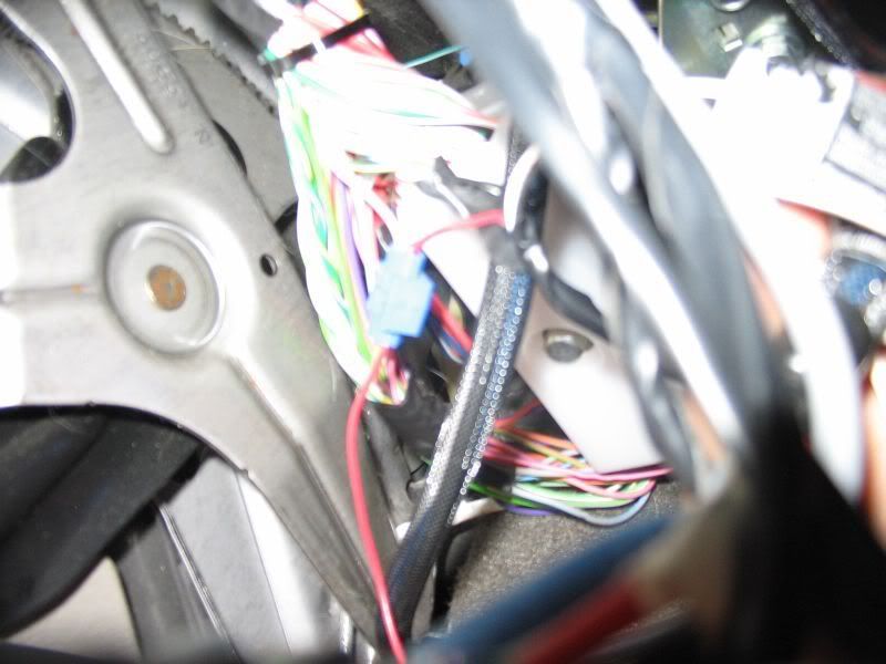
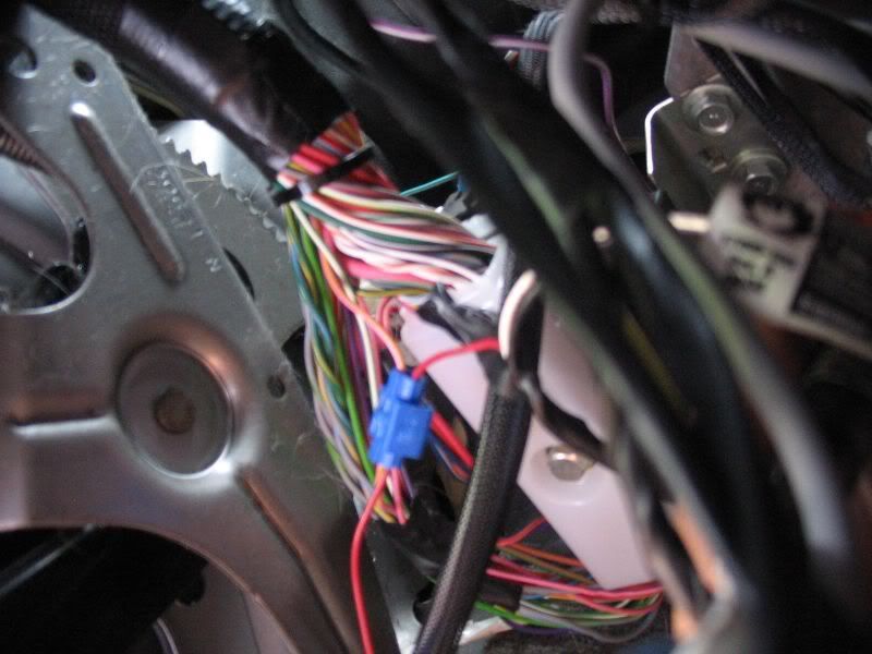
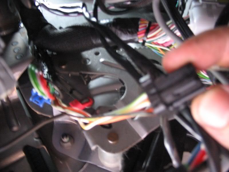
13. Locate the wiring harness plug for the light switch from behind the dash. Push the tab at the top down and pull the connector from the switch. You want to connect the white wire to the BROWN/BLACK tracer wire with the same methods as above.
http://i198.photobucket.com/albums/aa222/8mpg_walbro/Fuel%20Pressure%20Gauge/036.jpg
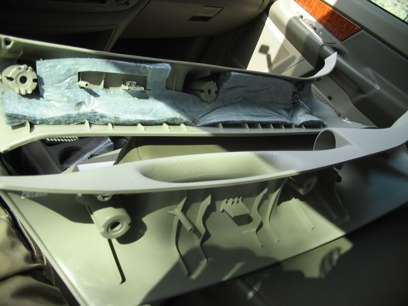
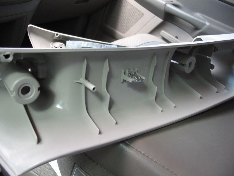
14. Get your new pillar pod and place it next to the stock one. You need one of the metal clips off the old one. Using a flat blade screwdriver, slide it under the metal clip. Using your finger pry on the other side and pull the clip off. They are a pain to get off and have little spikes that are designed to keep it from pulling off. Push it down on the new pillar pod tab at the top of the pillar.
http://i198.photobucket.com/albums/aa222/8mpg_walbro/Fuel%20Pressure%20Gauge/037.jpg
http://i198.photobucket.com/albums/aa222/8mpg_walbro/Fuel%20Pressure%20Gauge/039.jpg
15. Grab the gauge and put it into the pillar pod. Using the supplied rubberband, slide it around the gauge on the back side of the pod. Push the rubberband forward until it holds the gauge. Push the rubberband into any voids between the gauge and the pod if possible to get a firm seal
http://i198.photobucket.com/albums/aa222/8mpg_walbro/Fuel%20Pressure%20Gauge/040.jpg
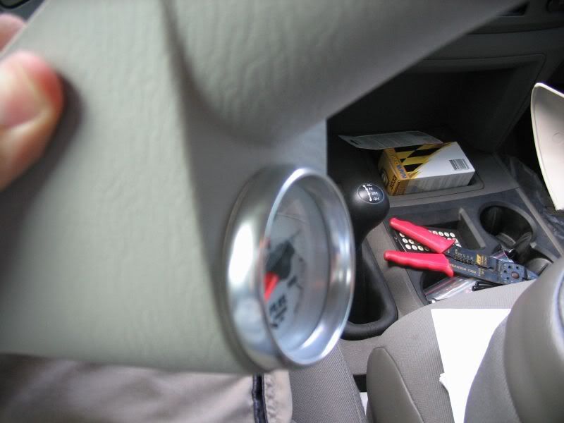
http://i198.photobucket.com/albums/aa222/8mpg_walbro/Fuel%20Pressure%20Gauge/041.jpg
http://i198.photobucket.com/albums/aa222/8mpg_walbro/Fuel%20Pressure%20Gauge/042.jpg
16. Connect the wiring harness to the back of the gauge. To reinstall the pillar pod, it goes it like it came out. Angle the pillar pod towards the center of the truck and slide the bottom tabs of the pillar pod back into their holes in the dash. Then rotate the pillar left. Make sure not to crush the wires when reinstalling. Try and push the pillar pod into the door seal while installing.
http://i198.photobucket.com/albums/aa222/8mpg_walbro/Fuel%20Pressure%20Gauge/044.jpg
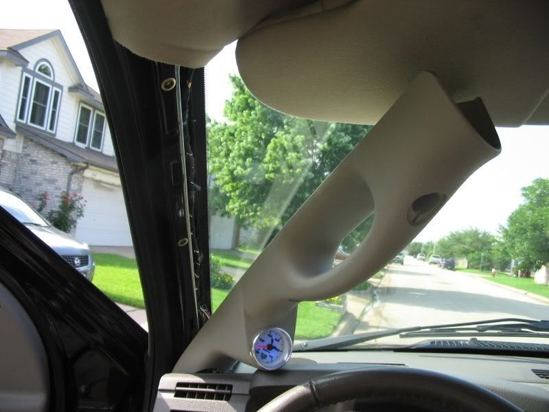
http://i198.photobucket.com/albums/aa222/8mpg_walbro/Fuel%20Pressure%20Gauge/045.jpg
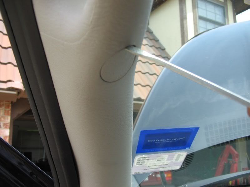
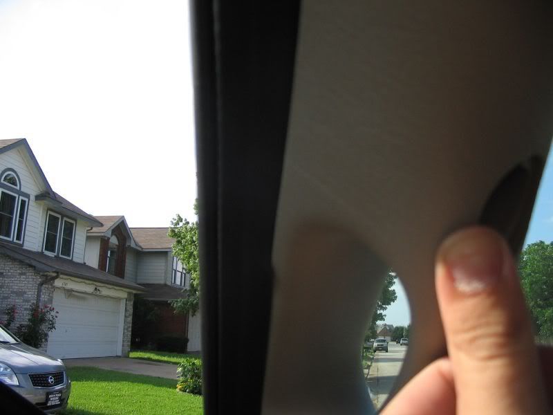
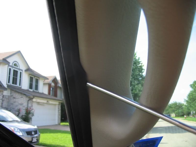
17. Using a small flat blade screw driver, pull the door weather-stripping over the pillar
http://i198.photobucket.com/albums/aa222/8mpg_walbro/Fuel%20Pressure%20Gauge/047.jpg
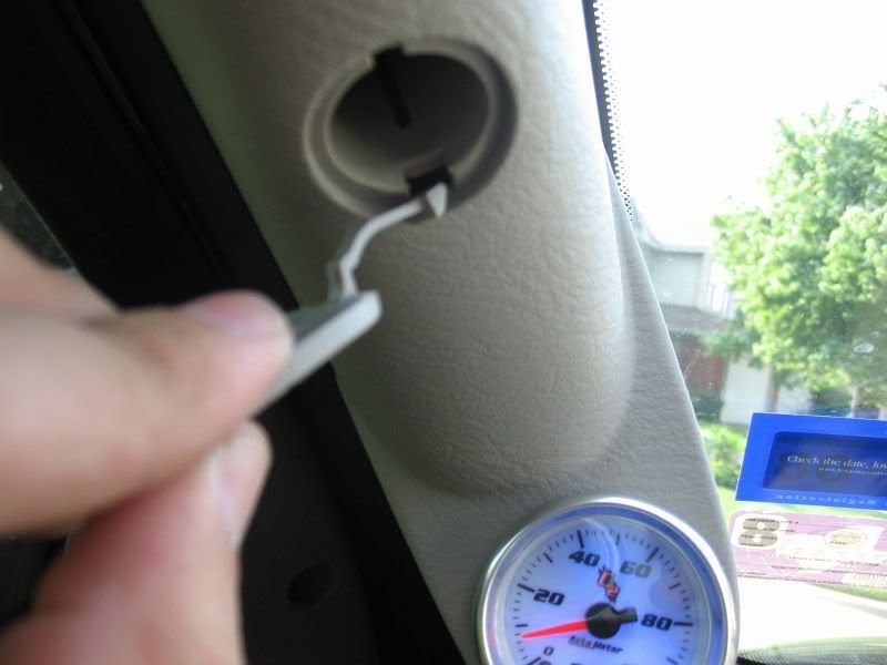
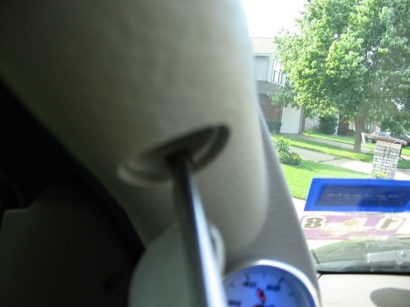
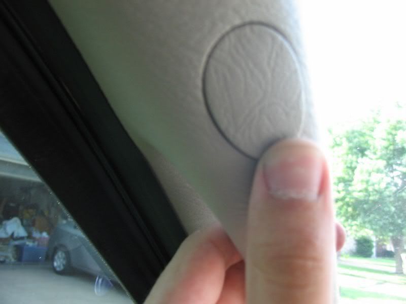
18. Push the bolt covers off the old pillar off with a flat blade screw driver. Be careful not to break the plastic. Push it off from the back side of the pillar, do not pull it. Then using the screwdriver, push the cover into its hole on the new pillar.
http://i198.photobucket.com/albums/aa222/8mpg_walbro/Fuel%20Pressure%20Gauge/048.jpg
http://i198.photobucket.com/albums/aa222/8mpg_walbro/Fuel%20Pressure%20Gauge/049.jpg
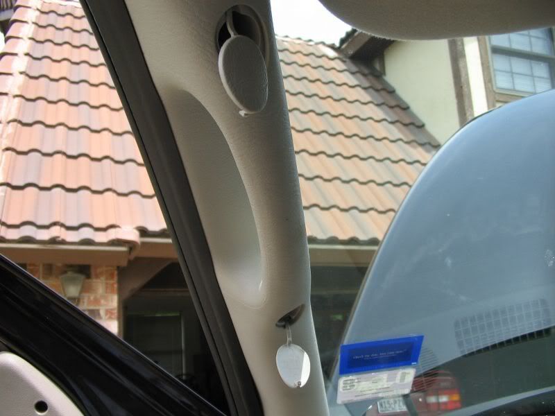
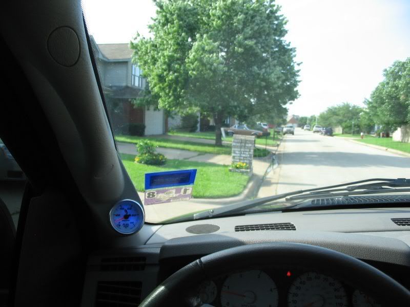
19. Using the factory bolts, tighten down the pillar. Push the bolt covers closed and you are DONE
http://i198.photobucket.com/albums/aa222/8mpg_walbro/Fuel%20Pressure%20Gauge/051.jpg
http://i198.photobucket.com/albums/aa222/8mpg_walbro/Fuel%20Pressure%20Gauge/052.jpg
http://i198.photobucket.com/albums/aa222/8mpg_walbro/Fuel%20Pressure%20Gauge/053.jpg
http://i198.photobucket.com/albums/aa222/8mpg_walbro/Fuel%20Pressure%20Gauge/054.jpg
THE END
--Iker42 17:19, 9 July 2007 (EDT)